Designing for plastic injection molding is like raising teenagers—some parts (and some teens) are more challenging than others. But by following a few simple rules, even the most difficult of these challenges can be overcome (parenting aside).
For injection molding, there are some common troublemakers during part design:
- Clips and snap fits
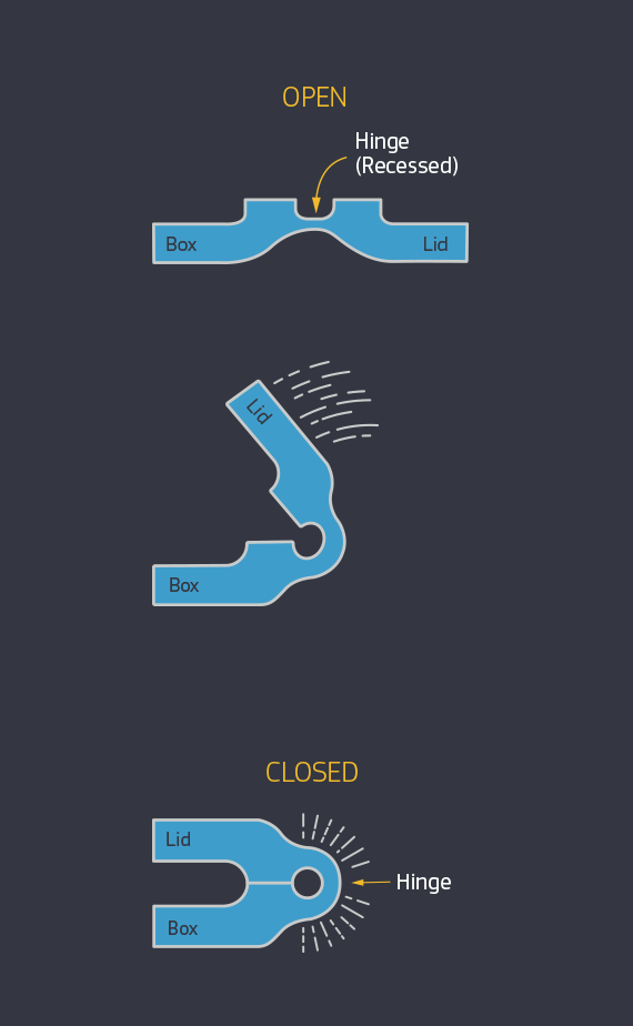
- Living hinges
- Bosses and standoffs
- Text on parts
- Overmolding
Look familiar? This list just happens to correspond with some of the more engaging features you can incorporate into your part designs, which is one reason why it’s so important to master them. Another is that, depending on your application, these features often provide more functional and aesthetic parts while reducing production costs. The following tips and techniques will help you do just that.

Clips and Snap Fits
There are plenty of examples where molded parts need a clip or snap-fit. The cover for an electronics device. A snap-on lid for a toolset. Both rely on a flexible, hook-like piece of material that extends into and catches on a female pocket or slot in the mating part. In either case, probably the best way to create these features is with a sliding shutoff, which as the name implies slides into the mold and prevents material from flowing into the desired area. This design also requires a hole in the part beneath the snap, the portion of the mold that passes through the part shutting off with mating features, which creates the snap fits.
However, this approach requires that the part feature is aligned with the direction of mold opening and that a relief hole at the base of the clip is allowable. An additional draft may also be required. If none of these are feasible, a side-action might be possible, but this must be aligned with the mold’s parting line and oriented perpendicular to the pull direction. Additionally, the side action must be accessible and remain in constant contact with the part.
Finally, hand-loaded inserts can be used. These are small chunks of machined metal that must be manually inserted and removed from the mold at each cycle. And consider the material—a flexible polymer-like ABS makes a better clip than does acrylic or PEEK, although some clever design tweaks such as adjusting the clip length or its geometry can get around many material constraints. Check with Protolabs’ applications engineers for other design tweak ideas (see customer service phone number and email address below).
Note: This whole discussion on clips applies equally well to any undercut or recessed part feature. This includes O-rings, side holes and pockets, windows, and so on. Based on the orientation of the part feature relative to the mold pull and parting line, various advanced molding techniques such as side-actions, telescoping shutoffs, inserts, and pins might be needed. All are perfectly acceptable and well-understood solutions, although, due to the added complexity, some of these resolutions may have an effect on molding and part cost.