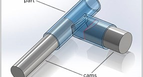
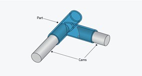
All sorts of reasons exist to create channels within a plastic part. Channels, tunnels, and holes can convey liquids, gases, or, in some cases, even solids; we often see them in parts for medical devices. Channels are formed in injection-molded plastic parts with cores or pins projecting from a mold half or cam. At FacFox these pins can be milled out of the mold block or a more robust steel pin can be inserted after milling. An interesting challenge arises when two channels meet within the body of a part. The challenge is forming a reliable shutoff where the two pins meet. The seemingly logical way to do that would be as shown in Figure 1.
The problem with this approach is that it leaves razor-thin edges where the pins meet, and such delicate features will risk becoming damaged in normal mold operation and pressurized injection of resin. Once these thin edges are damaged, the resin can leak into the resulting space between the pins leaving a “flash” that, being on an interior surface, will be particularly difficult to remove.
Of course, in designing a part you do not overtly specify how pins will be used to form your channels, but intersecting channels would require exactly this kind of shutoff. If you inadvertently create this potentially problematic shutoff, your design analysis should highlight it for you. Our quoting system does not specifically recognize channel intersections, but it does look for unacceptably thin edges, telling you that you have created a “sharp point” in the mold and highlighting the area that must be corrected. You will have to fix the problem before proceeding; fortunately, there are a few simple ways to redesign such a shutoff to eliminate the problem.
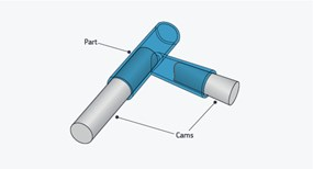
Taper the Side Channel
As shown in Figure 2, you can taper the pin forming the channel so that the thinnest edge of its concave face contacts the side of the main channel rather than its maximum extents. As a result, the thin edges of the concave tip will be lessened and therefore more robust and able to withstand the pressures of molding.
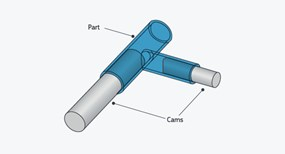
Reduce the Diameter of the Side Channel
You can accomplish the same thing by making the overall diameter of the side channel smaller than that of the main channel (see Figure 3). As in the previous example, this reduces the thinnest parts of the concave surface, reducing the likelihood of damage in the course of molding.
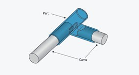
Bevel the Thin Edges of the Concave Surface
Figure 4 shows a way to eliminate extremely thin edges on a pin’s concave end when both channels are of the same diameter and tapering is not an option. In this case a chamfer is milled between the outside surface of the side-channel pin and its concave face. This blunts the thin edges of the concave tip by removing them from the top and bottom surfaces of the other pin without reducing the diameter of the side channel.
Create an Oversize Side Channel
Finally, if your design cannot tolerate restriction of the passage from the side channel to the main channel, you can increase the size of the side channel and then use one of the above methods while maintaining a full-size passage from one channel to the other. In essence, you will have created an oval passage that is narrower across the width of the main channel but wider along its length (see Figure 5).
