Support structures are one of the most important elements for successfully producing 3D printed parts. While a key advantage of 3D printing is its ability to create freeform and intricate geometries, much of the design freedom offered by 3D printing wouldn’t be possible without the use of support structures.
Supports are vital for preventing distortion and collapse within a part, among other uses. In this tutorial, we’ll be taking a deep dive into the world of support structures, the requirements for different technologies and how to minimize their usage.
What are support structures?
Used with almost all 3D printing technologies, support structures help to ensure the printability of a part during the 3D printing process. Supports can help to prevent part deformation, secure a part to the printing bed and ensure that parts are attached to the main body of the printed part. Much like scaffolding, supports are used during the printing process and then subsequently removed.
Parts with complex design features like overhangs, holes and bridges are more challenging to print. Since these features are likely to collapse if not supported, support structures can aid in preventing collapse during the printing process.
Supports can also work as heat dissipators in processes where high temperatures are involved, as is the case with metal 3D printing. With metal AM technologies, support structures help to draw heat away from the part preventing residual stresses that occur due to high temperatures experienced during the printing process.
When do you need support structures?
Almost all 3D printing technologies will require you to consider support structures to some degree. So let’s have a closer look at how 3D printing methods differ in using supports:
Metal 3D Printing
Powder Bed Fusion (SLM, DMLS, EBM)
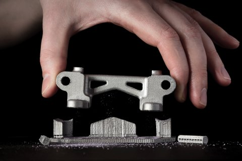
With metal powder bed fusion technologies, 3D printed parts are surrounded by loose powder. However, these technologies will always require supports to ensure that they are anchored to the base plate and to mitigate the effects caused by residual stresses.
Supports can be added to the contact area between the bottom of a printed part and the print bed, which is where the highest concentration of residual stress is found. This helps to draw heat away from the part, thereby minimizing thermal distortion which can lead to cracking, warping, sagging, delamination, and shrinkage.
Take a look at our guide to common issues faced in metal 3D printing to find out how to avoid these problems.
Direct Energy Deposition (DED)
Direct Energy Deposition covers a series of metal 3D printing technologies that work by melting and fusing material to create a part. Like powder bed fusion technologies, parts printed using DED will always require support structures to ensure part stability, the printability of complex features and for thermal dissipation.
Design
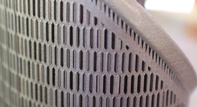
When designing supports for parts produced with powder bed fusion techniques, it’s important to ensure that they are easy to access, otherwise they cannot be removed during the post-processing stage. Supports for metal parts are generally printed as lattice structures. In this manner, they act as a heat sink, transferring heat away from the part, allowing it to cool in a more controlled manner and avoid distortion as well as save material costs and build time.
Adding more supports will generally result in a more accurate part, but this will also add greater costs and post-processing time.
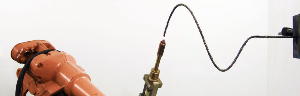
Interestingly, Dutch company MX3D has created a metal 3D printing tool that can print metal parts without supports, by combining a multi-axis robotic arm with a welding machine.
Support removal
Support removal for metal parts is typically more difficult than polymer-based processes, and cutting tools will typically be required. Additionally, if the appearance of the finished part is important, metals parts will also require post-processing (e.g. sanding) to achieve a smooth surface finish.
Stereolithography (SLA)
Stereolithography works by using a light source to solidify liquid resins. For this technology, support structures are required to securely attach a part to the print bed and to prevent warping.
Supports used in SLA are very thin and, to save material, only slightly touch the part. This means that they are quite easy to remove manually, either by hand or using pliers. However, since removing supports can leave marks on the final part, sanding will be needed to ensure a smooth surface finish.
Design
SLA is very often used for applications where appearance or a smooth surface finish is required, such as visual prototypes, moulds and hearing aids. If this is the case, it’s important to design your part to ensure that the forward-facing areas of your print are not in contact with support structures. This is where part orientation comes in.
Part orientation is an important consideration in the design stage, as reorienting a part can help reduce the amount of support needed. For example, horizontal orientation for a tubular part will take up more space and therefore require more supports. In contrast, a vertical orientation of the same part will ensure that the part is attached to the build plate with minimum supports needed.
Fused Deposition Modelling (FDM)
With Fused Deposition Modelling, parts are created by extruding heated filament layer by layer. As each layer cools, it solidifies, bonding with the previous layer.
Design
Each layer in the FDM process is printed slightly protruding so that it can expand beyond its previous layer width. This means features with angles up to 45° can be created without supports. However, when an FDM part has an overhang of more than 45° or includes features like bridges and protruding surfaces greater than 5mm, supports will be needed. FDM supports can take the form of a lattice structure or, alternatively a tree-like structure.
Support removal
One of the techniques used to remove supports from FDM prints is a dissolvable solution. Typically, industrial FDM 3D printers (with two print heads) use dissolvable support materials like Polyvinyl Alcohol (PVA) and High-Impact Polystyrene (HIPS). These are added by a separate extruder.
While PVA dissolves in water, it can be affected by temperature changes, which can lead to blockages int he printer head. HIPS dissolves in limonene instead of water, and is less susceptible to temperature changes.
Using dissolvable supports is hands-free and doesn’t require further sanding and polishing to remove the marks left by supports. On the flip side, this process can be time-consuming (taking several hours) and costly.
Material Jetting
When using Material Jetting 3D printers, the supports are always required for overhangs, regardless of the angle. However, these supports are typically built in a different material, which is either water-soluble or can be easily removed afterwards using pressurised water or by immersion in an ultrasonic bath.
Selective Laser Sintering and Binder Jetting
Selective Laser Sintering and Binder Jetting are both powder-based technologies that typically do not require any support structures. This is because with both technologies, printed parts are encapsulated in the loose powder which takes the role of the support structure.
The downside of supports
Despite the necessity of support structures, they will add additional printing time and material costs to the overall production process.
Material costs: Support generation will require additional material during the printing process, increasing both time and material costs. It’s also important to note that supports are not reusable and usually disposed of, resulting in a wasted material.
Limited geometric freedom: when removing supports manually, hand or tool access needs to be factored in when designing supports. This, however, can restrict you from designing certain geometries which will require support structures but cannot be reached by hand or tool.
Extra time: designing a part to accommodate support structures and subsequently designing the supports themselves requires extra time. Although there are software offering automated support generation, creating support structures for industrial applications will still need some manual touchup and a certain level of design expertise.
Additional post-processing: Once a part is complete, supports will have to be removed, sometimes manually, increasing the time needed for post-processing.
Risk of damage: Bear in mind that removing supports may leave marks on the surface of a part, which can affect its dimensional accuracy and aesthetics. Additionally, when supports are incorrectly placed, for example on fine features, these can break off along with the support structure – ruining a part altogether.
4 ways to reduce supports
It’s generally good practice to reduce the number of supports needed as much as possible. This will help to save on both material costs and production time. Here are 4 top tips on how to minimise their usage, saving you printing time and material.
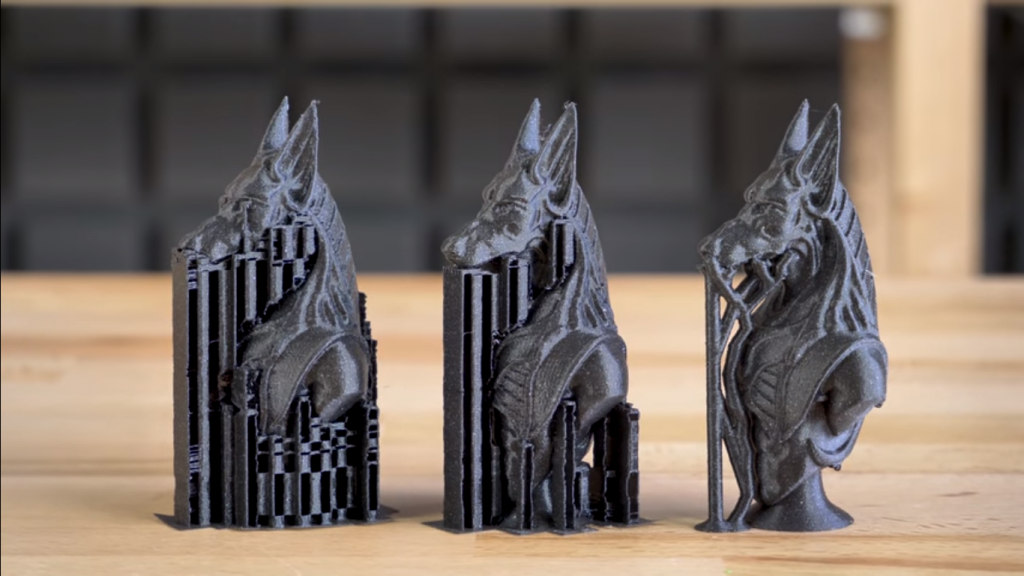
1. Choose the optimal part orientation
To date, experimenting with part orientation is one of the best ways to reduce the number of support structures needed. Choosing the right part orientation can have a significant impact on the printing time, costs and a part’s surface roughness.
Depending on a part’s orientation (vertical, horizontal or angled), there may be fewer or more support structures needed. Consider a part printed in the shape of the letter T. In its ordinary position, both branches of the letter will collapse without support structures in place. If the part is oriented differently, i.e. ⊥, then supports will not be required.
This example demonstrates that a part can be built up in different ways. Each side of a part can have a different surface attached to the print bed, meaning that the need for supports can vary and be heavily dependent on the orientation of the part.
Another example: when designing a part with hollow tubular features, horizontal orientation will take up more space, while a vertical or angled orientation will save space and reduce the amount of supports needed.
2. Optimise your support structures
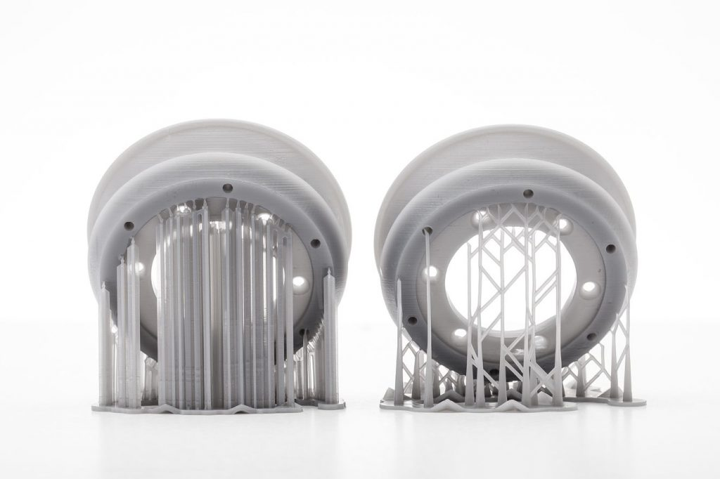
When supports cannot be avoided, they should be optimised to use as little material as possible, and to speed up the printing process. For example, topology optimisation can be used to design, supports with lattice structures, reducing the support volume of and saving material.
With many 3D printing processes, commonly used support generation techniques are limited to producing strictly vertical structures. These are not space-efficient, particularly when there are many regions to be supported high above the print bed.
Creating tree-like support structures instead may be a viable alternative. Such supports look like a branching tree and arguably consume 75 % less material compared to straight vertical structures. Autodesk Meshmixer is one of the software tools that can be used to create such structures for FDM, SLA and DMLS processes.
3. Use fillets and chamfers
Using fillets and chamfers can be an alternative solution to creating support structures for overhanging surfaces greater than 45 degrees.
A chamfer is a sloped or angled corner or edge, and a fillet is a rounded corner or edge. Essentially, these features turn an angle that is greater than 45 degrees into an angle that is 45 degrees or less and can be added to either the interior or the exterior of a part.
4. Split your part
For very complex 3D models, it can often make sense to print the part separately and assemble them together afterwards. This will not only reduce the amount of supports but also speed up the printing process while saving material.
However, keep in mind that if the 3D printed parts need to be assembled, they have to be printed in the same direction so that they fit each other properly.
3D printing supports: a necessary evil?
Support structures have long been considered a necessary evil in 3D printing. However, recent advancements in hardware and software are slowly changing this perception.
For example, metal 3D printer manufacturer, Desktop Metal has recently developed and patented ‘separable supports’ for its Studio and Production Systems. These supports for the 3D-printed metal parts can be removed by hand. Desktop Metal’s separable supports work by using ceramic powder as the interface layer between the part surface and the support structure. Following the sintering process, the ceramic layer is dissolved so that the support can be easily removed from the part.
Another company aiming to simplify and speed up the support removal step for 3D printed parts is PostProcess Technologies. The company offers a range of automated, hands-free support removal solutions for parts additively manufactured by FDM, SLA, PolyJet, and CLIP technologies.
However, one company has stepped even further. Velo3D, the company behind the powder-based Sapphire system, has powered its system with a technology it calls Intelligent Fusion, which enables complex metal parts to be printed with few to zero supports. Using Velo3D’s proprietary simulation software and closed-loop monitoring, parts can be produced with up to five times fewer supports needed compared to other powder-bed metal systems.
Overall, optimising support design and removal are key challenges in making 3D printing workflows faster and simpler. But, as seen from the examples above, the industry is constantly developing solutions to overcome the challenges. Alongside any technology, however, will be the need for greater skill and know-how for successful implementation. Hopefully, this guide has expanded your knowledge on how to use support structures in 3D printing more efficiently, helping to turn them from an enemy into an ally.