Check out our 3D printer calibration guide to learn in 3 steps how to calibrate your 3D printer and fine-tune your slicer settings.
Dialing in the First Layer
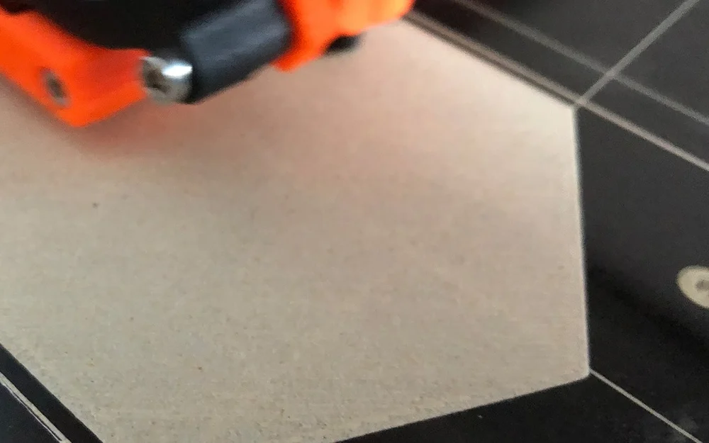
Having a good first layer is crucial to having a good final print. If your nozzle is too close to the bed, your first layer will be squished and possibly destroyed, meaning you’ll have to cancel your print. Meanwhile, if your nozzle is too far away from the bed, your print will lack adhesion and likely fail.
You can improve your first layer by tuning the Z offset. This is a value that essentially tells your printer how far to move the Z-axis from the Z endstops – in other words, from the bed.
The goal, in a nutshell, is for your first layer to stick perfectly to the bed. If you see that your first layer is squished or that the nozzle digs into it, you should increase the Z offset. On the other hand, if your first layer is peeling up from the bed, then you want to lower the Z offset.
Calibrating the Stepper Motors
3D printers use stepper motors, which rotate by small steps in order to move axes or the extruder a certain distance. For example, if one rotation is 100 steps, then the motor must rotate 50 steps in order to turn half of a rotation. This allows for very precise rotation control.
For a 3D printer, calibrating your stepper motors involves determining the relationships between steps and distance. In order to calibrate the extruder, you’ll need to make sure that your 3D printer is extruding the right amount. To do this, you will have to send a few G-code commands to your printer.
Step 1: Prepare Your Values
In this step, we’ll compare your printer’s settings with how it actually prints. If there’s a discrepancy, we’ll do a few calculations to correct it.
- First, retrieve all of your printer’s settings by sending it the command
M503. Part of the output should look like the following:Steps per unit: M92 X100.00 Y100.00 Z400.00 E140.00 - Take note of these values. The first three correspond to the number of steps that the stepper motors take to move one millimeter in the X, Y, and Z directions, respectively. We aren’t concerned with those at the moment, but we’ll need them later. Right now, we care about the last value, which is the number of steps that the extruder motor takes per millimeter of extruded filament. We’ll call this number A.
- Next, insert some filament and make a mark about 50 mm above the top of the extruder. Measure the exact value with calipers and write it down. Let’s call this number B.
- Next, extrude 10 mm of filament and again measure the distance from the top of the extruder to the marked point. If we call this value C, then B – C is the amount of filament that was extruded.
NUMBER CRUNCHING
If B – C = 10 mm, then the extruder is already calibrated correctly! If not, we need to update the extruder’s steps per millimeter.
Compute the value D = 10*A / (B – C). This is the new number of steps per millimeter for the extruder. For best results, it may help to repeat the process for measuring D multiple times, and then take the average.
Step 2: Calibrate Your 3D Printer Extruder
In order to actually carry out the calibration, you need to tell the printer the new value:
- Send the command
M92 E[D]to the printer. While this command tells the printer the new value, it does not actually save it. - Send the command
M500to save the new value.
Now, the extruder should be calibrated correctly.
EXAMPLE
Let’s suppose that before our test extrusion, we measured the distance between the marked point and the top of the extrusion to be 53.10 mm, and after the test extrusion, we measured the distance to be 42.80 mm. Then B-C = 10.30 mm.
If the original number of steps per millimeter for the extruder was 140, then we would send the command M92 E135.92 because 10*140/10.30 = 135.92.
TIPS
In this case and, later, when you calibrate the axes, do not expect your results to be perfect. There’s bound to be variation after you confirm that your calibration is correct, but as long as you are pretty close (within a few percent) to the desired value, your printer should be well-calibrated.
Step 3: Calibrate Your 3D Printer Axes
After calibrating the extruder, it’s also important to calibrate the axes of the printer. Calibrating the axes is similar to calibrating the extruder, but requires that you actually print something.
Please keep in mind that calibrating the extruder should always be done before the axes because the former can affect the size of printed objects. As the axes calibration involves measuring prints, you want to make sure the extruder is adjusted beforehand.
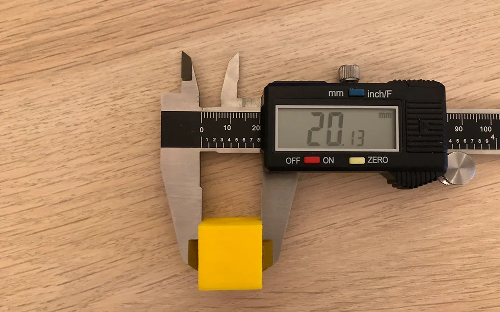
For the axes calibration, you can print a small cube, for example. Either design one yourself in the CAD software of your choice, such as OpenSCAD, or check out the models in Best 3D Printer Calibration Cubes of 2021.
HOW TO DO IT
After the cube has finished printing, measure each dimension. For each axis, repeat the computation you did for the extruder, D = 10*A / (B – C), but replace the variables as follows:
- (B – C) with your measurement
- the number 10 with the target value of that measurement
- A with the M92 value for that axis (i.e. the values you noted in Step 1 after sending the command
M503)
Then, send the appropriate M92 commands to the printer, again replacing E by the letter corresponding to the axis you need to set.
EXAMPLE
Suppose our cube is supposed to be 20 mm on each side but we measure 20.30 mm in the X-direction. If our M92 value for X was set to 100.00, then we would update this value by sending our printer the command M92 X98.52 because 20*100 / 20.30 = 98.52.
TIPS
As with the extruder, it helps to make multiple measurements and take their average. In this case, however, you don’t need to print multiple objects. You can simply measure the cube at different positions (along the same axis).
Fine-Tuning Filament Settings
Every roll of filament is different. Plastics from different manufacturers, and even different colors of the same material, have different properties.
In order to get the best prints possible, you’ll need to fine-tune your filament settings. Usually, you can get good prints just by using the settings recommended by the filament manufacturer.
For best results, however, you should follow these steps every time you open a new roll of filament.
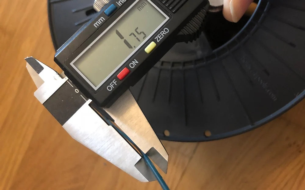
Step 1: Measure Your Filament
The diameter of a roll of filament often differs from the diameter reported by the manufacturer by up to a few percent. The tolerance in diameter is usually printed on the spool. So, it’s important to use calipers to measure the true diameter of the filament:
- Measure your filament at a few (at least three) places along the spool.
- Take the average of your measurements.
- Enter this result as the filament diameter in your slicer.
Getting this number right is important because it helps to ensure that your printer will extrude the right amount of filament.
Step 2: Find the Right Print Temperature
You can find the right temperature to print at by printing a “temperature tower”. There are many different options available online, but the basic idea is the same for all of them. They are separated into blocks at different heights, where each block should be printed at a different temperature. By analyzing the blocks after printing, you can determine the best temperature at which to print your material.
Printing a temperature tower, however, can require a little bit of work. If your slicer does not allow you to print with different temperatures at different heights, you’ll have to manually edit your G-code before printing. This requires inserting G-code commands to set the extruder temperature. Such commands begin with M104.
HOW TO DO IT
- First, determine the height of each block. Call this number H, so that the different blocks start at height 0, H, 2H, 3H, and so on.
- Then, open your G-code file in the editor of your choice. You want to look for commands that tell your printer how to move, which begin with
G1. Your G-code file will contain an enormous number of these. - Find the first G-code command of the form
G1 Z[H]. (It may also contain X and Y movements.) - Before this line, insert the line
M104 S[T]where T is the temperature of the block that begins at height H. - Repeat this for each block, with the appropriate temperature.
- Once you’re done, print the updated G-code file.
EXAMPLE
If the blocks have heights of 1 cm (10 mm) and the temperatures go from 185 °C to 220 °C in increments of 5 °C, then you should find the first command containing G1 Z10 (the first command that brings the hot end to a height of 10 mm). Immediately before this line, you should set the hot end to 190 °C by inserting the line M104 S190.
FINAL STEPS
Once you have printed a temperature tower, examining the different blocks will allow you to determine the best temperature at which to print your material. Simply pick the temperature that looks the best. Set this as the printing temperature in your slicer, and you’re ready to go!
A Little More Torture
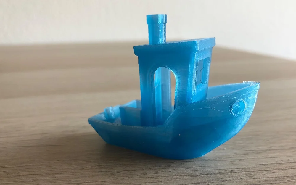
We’ve described the most important ways to calibrate your printer’s settings and some slicer settings for your filament. However, there are numerous other settings that you can also change to improve your prints. In order to get an overview of what their printer is good and not so good at doing, people often use “torture tests”. Printing and perfecting such prints can help with problematic areas like bridges and overhangs. They’re also helpful in diagnosing a variety of problems.
While the most popular torture test is 3DBenchy (usually just called “Benchy”), you can find plenty of others by searching for torture tests on your favorite STL site. We won’t go into detail here because every torture test is a little different, but most come with instructions on how to diagnose problems and points of failure.
Source: https://all3dp.com/2/how-to-calibrate-a-3d-printer-simply-explained/