Understanding G-code commands will unlock the next level of 3D printing. Read on to quickly learn the basics of this code!
Simply put, G-code is a programming language for computer numerical control (CNC). In other words, it’s the language spoken by a computer controlling a machine, and it communicates all commands required for movement and other actions.
While G-code is the standard language for different desktop and industrial machinery, we might be most familiar with it through our 3D printers. You may not have dealt with it so far, and that’s actually normal since 3D slicers generate the code “automagically”.
Yet, if you want to develop a deeper understanding of 3D printing, it’s essential to learn the basics of G-code. This knowledge will allow you to troubleshoot and control print processes much better, while also enabling the customization of 3D printer firmware like RepRap and Marlin.
In this article, we’ll cover the basics of G-code, including how to read, understand, and write a few lines of commands, providing a solid background for even absolute beginners in coding. Without further ado, then, let’s start from the beginning!
What Is It?
For those strangers to programming in general, think of G-code as sequential lines of instructions, each telling the 3D printer to perform a specific task. These lines are known as commands, and the printer executes them one by one until reaching the end of the code.
While the term “G-code” is used to reference the programming language as a whole, it’s also one of two types of commands used in 3D printing: “general” and “miscellaneous” commands.
General command lines are responsible for types of motion in a 3D printer. Such commands are identified by the letter ‘G’, as in G-commands. Besides controlling the three plus axes movement performed by the printhead, they’re also in charge of filament extrusion.
The miscellaneous commands, on the other hand, instruct the machine to perform non-geometric tasks. In 3D printing, such tasks include heating commands for the nozzle and bed and also fan control, among many others, as we’ll see. Miscellaneous commands are identified with the letter ‘M’.
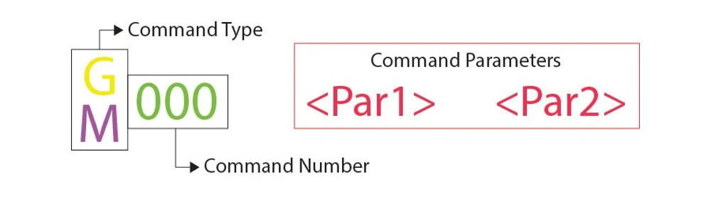
Every G-code command line follows a certain syntax. Each line corresponds to only one command, which can lead to codes that are awfully lengthy.
The first argument of any given line is the command code itself. As we have seen, it can be either a ‘G’ or an ‘M’ code type, followed by a number that identifies the command. For instance, “G0” corresponds to a linear move command.
Next comes the parameters that more accurately define the command. For a G0 linear move, these parameters include the final position and how fast it moves, also identified by upper-case letters. Each command has its own set of parameters as we’ll see soon.
A Note on G-code Comments
Before we get started, when we go over the various commands, you’ll see semicolons after a letter and number that explain what the code does. Here’s an example of a line that has a code comment:
G1 X25 Y5 ; I am a code comment!
Programmers often need to include explanations in plain English so that other programmers can understand certain lines or sections of code. It might also happen that you forget why you coded things in a certain way, resulting in a difficult time figuring things out again.
To solve this problem are code comments. Comments include anything (on the same line) following a semicolon and are completely ignored by the machine when it executes the G-code. In this way, they are purely meant for programmers’ eyes.
IMPORTANT COMMANDS FOR 3D PRINTING
As there are literally hundreds of G-code commands, we’ll cover the most basic and important ones in the following sections. Once you get the hang of it, you’ll be able to explore other commands from reference sheets on your own.
G0 & G1: Linear Motion
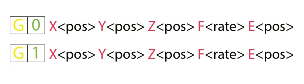
The G0 and G1 commands both perform linear movements. By convention, G0 is used for non-extrusion movements like initial and travel moves, while G1 encompasses all the extruding linear motion.
Both commands function the same, though. The parameters for G0 or G1 include the final positions for all the X-, Y-, and Z-axes, the amount of extrusion to be performed during the move, and the speed, specified by the feed rate in the set units.
Example
G1 X90 Y50 Z0.5 F3000 E1 tells the printer to move in a straight line (G1) towards the final coordinates X = 90 mm, Y = 50 mm, Z = 0.5 mm at a feed rate (F) of 3,000 mm/min while extruding (E) 1 mm of material in the extruder.
Most linear moves are performed within a single layer, meaning that the Z coordinate is usually omitted from the command line.
G90 & G91: Absolute & Relative Positioning
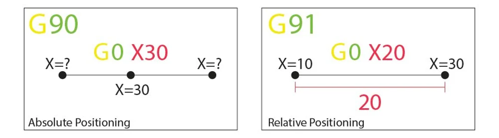
The G90 and G91 commands tell the machine how to interpret coordinates used for movement. G90 establishes “absolute positioning”, which is usually the default, while G91 is for “relative positioning”.
Neither command requires any parameters, and setting one automatically cancels the other. The way positioning works is quite simple, so let’s jump right in.
Example
Let’s say we want to move the printhead to X=30 in a line. In absolute positioning mode, that would look like this:
G90 ; sets absolute positioning G0 X30 ; moves to the X = 30 coordinate
This simple move would tell the printer to move the printhead so that it’s positioned at X = 30. Now, for a relative positioning move, we need to know where the printhead is currently. Let’s assume it’s at X = 10:
G91 ; sets relative positioning G0 X20 ; moves +20 mm along the X-axis
G91 first tells the machine to interpret the coordinates as relative to the current position (X = 10). Knowing that, the machine simply needs to move 20 mm in the X-axis positive direction, thus reaching X = 30, as we’d like.
G28 & G29: Auto Home & Bed Leveling
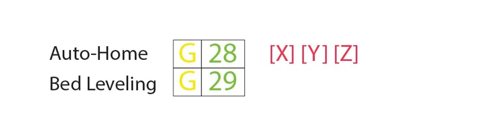
We call “homing” the process of setting the physical limits of all movement axes. The G28 command will perform this task by moving the printhead until it triggers end-stops to acknowledge the limits.
Homing is important not only for the machine to orient itself but also to prevent the printhead from moving outside the boundaries. The G28 command is usually performed before every print process.
Another command, G29, starts the automatic bed leveling sequence. There are many different methods for leveling a bed prior to printing, as this is usually set by firmware and not by the final users. For this reason, we won’t get into details surrounding the methods and command parameters. Just know that G29 is usually sent after an auto-home (G28) and should perform the automatic bed leveling as determined by the firmware.
Example
G28 X Y ; home the X and Y axes only
G28 ; home all axes
Specific axis can be individually homed by including X, Y, or Z as parameters. Otherwise, G28 alone will home all three.
G29 ; perform automatic bed leveling sequence
If you want to run an auto bed leveling sequence, remember to send G29 after performing the homing process.
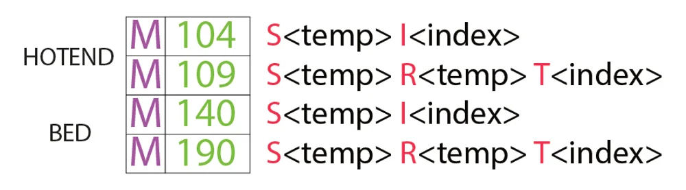
M104, M109, M140, & M190: Set Temperature
These are essential miscellaneous commands, which again, don’t involve any motion.
To start, the M104 command sets a target temperature for the hot end to reach and keep it until otherwise instructed.
Some of the parameters include the actual temperature value (S) and which printhead (T) to heat (for multiple extrusion setups).
Example
M104 S210 ; set target temperature for hot end to 210 degrees
This command line instructs the machine to heat up its hot end to 210 °C and assumes there is only one hot end in this extrusion setup. After setting the target temperature, the printer will go on to perform the next command line while heating the hot end.
Alternatively, if we wanted to wait until that target is reached before moving on to the next line, we can use the M109 command.
M109 S210 ; set target temperature for hot end to 210 degrees and do nothing until reached
Setting the bed temperature is very similar to the hot end, but instead with the M140 and M190 commands:
M140 S110 ; set target temperature for bed to 110 degrees
M190 S110 ; set target temperature for bed to 110 degrees and do nothing until reached
M106 & M107: Fan Control
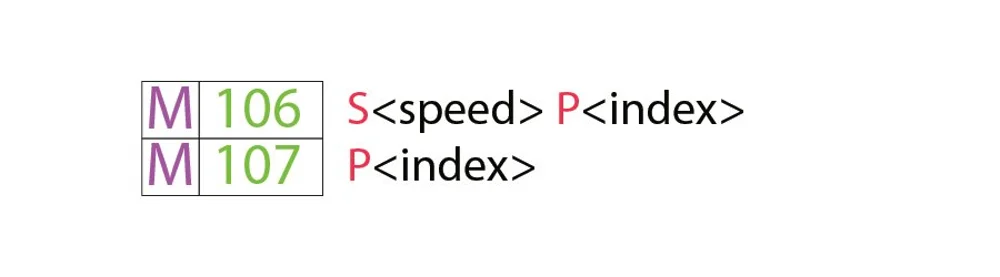
Yet another essential task for 3D printers, the miscellaneous M106 and M107 commands provide fan control.
M106 turns a fan on and sets its speed. This is especially useful for the part cooling fan, as different speeds are required during the printing process during the first layer and bridging.
The speed parameter must be a value between 0 and 255. A 255 value provides 100% power, and any number within this range will specify a percentage accordingly.
Example
M106 ; turn on a fan at maximum (100%) speed
M106 S128 ; turn on a fan and set it to 50% power
Multiple speed-controlled fans can be defined by the index (P) parameters, as each fan is assigned an index by the firmware.
Finally, the M107 command will power off a specified fan. If no index parameter is provided, the part cooling fan is usually the one to be shut down.
PROGRAM STRUCTURE
We’re now in a good position to look at an actual piece of code that’s used for 3D printing. G-code programs can be divided into three distinct sections, as we’ll see next.
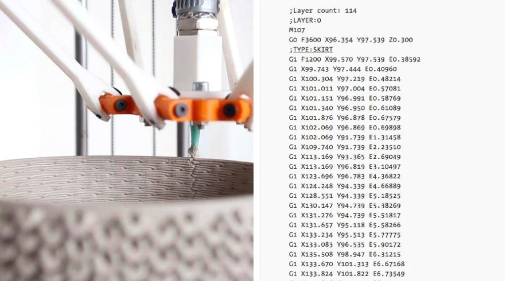
It’s worth noting that, if you use a text editor to open a G-code file generated by a 3D slicer, it might be that it won’t immediately start with G- or M-commands. For example, a slicer like Cura or Simplify3D starts code by including some of the printing process parameters defined previously within comments. These lines won’t affect the printing but instead present a quick reference for parameters like layer height, for example.
Phase 1: Initialization
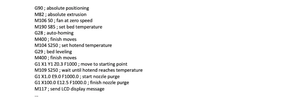
The first section of any program includes the preparation tasks required prior to starting printing the model. The following are the first six lines of initialization G-code commands from an actual 3D printing job.
G90M82M140 S80M104 S200G28G29
As we now know, the first line says that movements should use absolute positioning, while the second line tells the extruder to also interpret extrusion in absolute terms.
The third and fourth lines start heating the bed and nozzle to their target temperatures. Note that it won’t wait for the target temperature, meaning that the printer will auto-home and level the bed while heating up.
Some initialization routines (e.g. the one used by PrusaSlicer) include a nozzle purging process, like printing a single straight line before jumping into the printing process.
Phase 2: Printing
Here’s where the magic happens. If you look at a sliced G-code file, you’ll see that it’s impossible for us to make out what the nozzle is actually doing.
3D printing is a layer-by-layer process, so you’ll find that this phase includes many movements within the XY-plane while printing a single layer. Once that’s done, one tiny movement in the Z direction will define the beginning of the next layer.
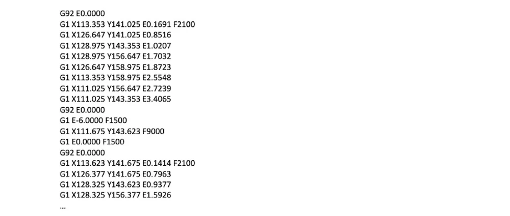
Here is an example of how G-code commands can look during the printing phase:
G1 X103.505 Y153.291 E4.5648 ; movement and extrusion in XY planeG1 X103.291 Y153.505 E4.5804 ; movement and extrusion in XY planeG1 Z0.600 F3000 ; change layerG1 X104.025 Y154.025 F9000 ; movement in XY planeG1 X95.975 Y154.025 E0.4133 F1397 ; movement and extrusion in XY plane
Phase 3: Reset the Printer
Finally, when printing is done, some final lines of G-code commands bring the printer to a reasonable default state.
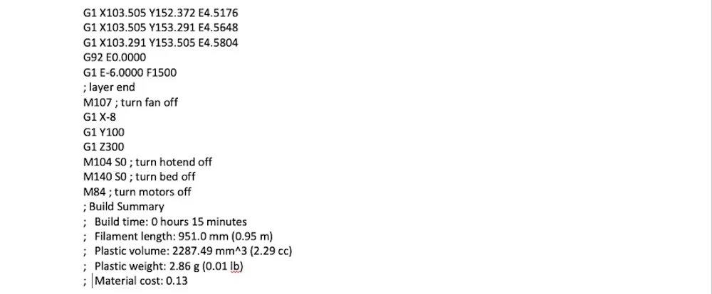
For example, the nozzle might go to a pre-defined position, the hot end and bed heaters are turned off, and the motors are disabled, among other actions.
M107 ; turn fan offG1 Z10 ; move nozzle away from printM104 S0 ; turn hot end heating offM140 S0 ; turn bed heating offM84 ; turn motors off
Terminal Inputs & Outputs
Until now, we’ve only talked about the computer sending G-code commands to the printer (usually transferred via an SD card). However, this isn’t the only method of communication.
Some control software, like Pronterface and OctoPrint, allows direct communication with the 3D printer, in which case you can input commands manually.
For obvious reasons, it wouldn’t be practical to print anything by sending lines of codes individually. But sometimes this method of communication is needed for other purposes, like retrieving valuable information for calibration or even when the 3D printer lacks a display screen.
For example, the M105 “report temperatures” command will retrieve the current nozzle and bed temperatures (which might then be displayed by something like OctoPrint).
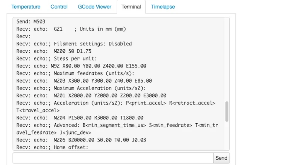
This communication is also very useful for seeing and changing EEPROM settings that are hardcoded at the firmware level. Parameters like a motor’s steps/mm, maximum feed rates, or PID can be visualized via M503 (“report settings”), changed manually, and then saved via M500 (“save settings”).
Writing G-code
By now, you should be able to read and understand G-code much better. Still, you can also benefit from writing it.
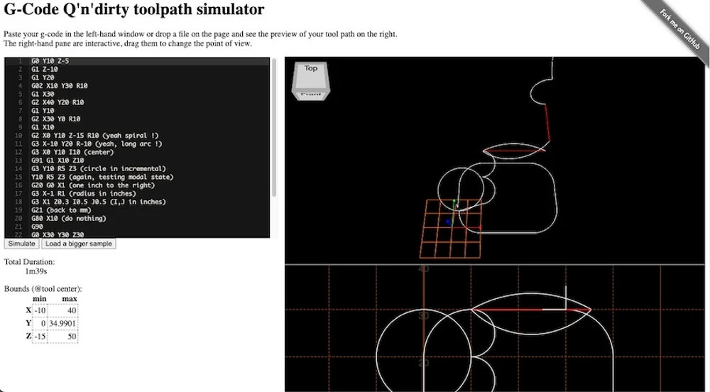
This G-code online visualization is a great tool for testing your skills, as you can write G-code commands and simulate them accordingly. It’s actually a lot of fun!
Looking at exported G-code files from slicers should also provide you with some insights as to how G-code works for 3D printing. Make sure to have a commands reference sheet by your side and explore the code!
Compatibility
We hope that, with an understanding of G-code commands, you become a more knowledgeable and powerful 3D printing user. While G-code isn’t the most complex computer language, it still requires a lot of practice and study.
Before wrapping up this article, it might be worth talking a bit about G-code compatibility.
There are many types of 3D printing firmware, and each might have different “flavors” of G-code. This can lead to major compatibility issues, as commands that work for one machine might not work for another.
Slicer software handles this by passing the code through machine-specific post-processing drivers. The post-processor detects the incoming code’s flavor and converts the code to something the firmware will understand.
With that said, we hope you enjoyed this brief guide. Happy coding!