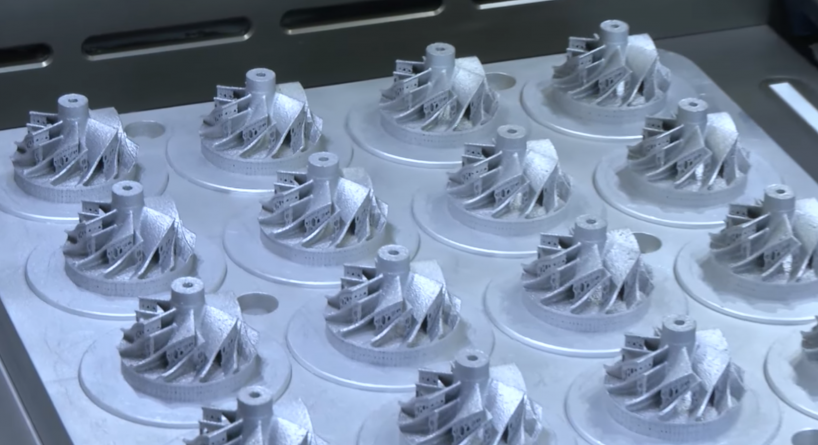
Metal 3D printing is advancing rapidly on all fronts: the technology is becoming more advanced, print speeds are increasing and there is a greater range of industrial materials than ever before. These advancements are opening up exciting new applications for the technology.
However, getting to grips with the available technologies and integrating them into existing workflows can be a challenge for many companies.
This guide aims to help you better understand metal 3D printing, from the technologies that are currently available to the technology’s benefits, limitations and key applications.
Metal 3D Printing: The Technologies
There are a number of different metal 3D printing technologies currently available on the market. While each has its benefits and limitations, all are united by the fundamental 3D printing principle of creating metal parts layer by layer.
Commonly used metal 3D printing technologies include:
- Powder Bed Fusion
- Direct Energy Deposition
- Metal Binder Jetting
- Ultrasonic Sheet Lamination
Powder Bed Fusion Technologies
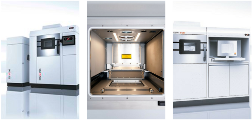
Of all of the metal 3D printing technologies, metal Powder Bed Fusion is perhaps the most established.
With Powder Bed Fusion technologies, layers of powdered metal are evenly distributed onto a machine’s build platform and selectively fused together by an energy source — either a laser or an electron beam.
There are two key metal 3D printing processes that fall under the Powder Bed Fusion category:
- Selective Laser Melting (SLM) / Direct Metal Laser Sintering (DMLS)
- Electron Beam Melting (EBM)
Selective Laser Melting and Direct Metal Laser Sintering
SLM and DMLS are the most dominant metal 3D printing technologies, with DMLS having the largest installed base worldwide, according to a report by IDTechEx Research.
With both SLM and DMLS, a powerful, fine-tuned laser is selectively applied to a layer of metal powder. In this way, metal particles are fused together to create a part.
An important requirement for both technologies is an enclosed build chamber filled with inert gas, such as argon. This prevents the oxygen contamination of the metal powder and helps to maintain the correct temperature during the printing process.
Electron Beam Melting
Another 3D printing process in the Powder Bed Fusion family is Electron Beam Melting (EBM). EBM operates similarly to SLM in that the metal powders are also melted to create a fully dense metal part.
To prevent contamination and oxidation of the powder, the EBM process takes place in a vacuum environment.
The key difference between SLM/DMLS and EBM technologies is the energy source: instead of a laser, EBM systems use a high-powered electron beam as the heat source to melt layers of metal powder.
EBM also tends produce metal parts with a lower level of accuracy when compared to SLM and DMLS. This is because the layer thickness in the SLM process is typically thinner (between 20 and 100 microns) than in the EBM (between 50 and 200 microns), resulting in more accurate prints.
Since an electron beam is typically more powerful than a laser, EBM is often used with high-temperature metal superalloys to create parts for highly demanding applications like jet engines and gas turbines. The metal parts produced are highly dense, and therefore ideal for the aerospace industry.
The high cost of EBM systems is something to consider for companies looking to invest in this technology. Additionally, since the technology relies on electrical charges, EBM can only be used with conductive metals, such as titanium and chromium-cobalt alloys.
Whether SLM/DMLS or EBM, all metal parts produced with Powder Bed Fusion technologies will require some form of post-processing. Post-processing is necessary, not only to improve the aesthetics of the part, but also to improve its mechanical properties and meet the exact design parameters, particularly for demanding applications.
Direct Energy Deposition
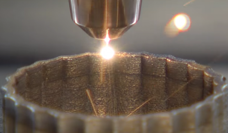
In contrast to Powder Bed Fusion processes, which typically produce smaller but highly accurate components, some proprietary DED methods can produce larger metal parts.
One example is US company Sciaky’s proprietary Electron Beam Additive Manufacturing (EBAM) technology, which is said to be able to produce parts larger than 6 metres in length.
DED technology is well-suited to repairing damaged parts like turbine blades and injection moulding tool inserts, which would be difficult or impossible to repair using traditional manufacturing methods.
Metal Binder Jetting
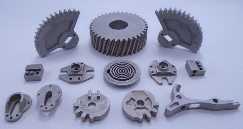
Metal Binder Jetting is one of the most cost-effective metal 3D printing technologies available on the market.
Similar to ink printing on paper, Metal Binder Jetting involves the use of a print head. This print head moves over the build platform, depositing droplets of a binding agent onto layers of metal powder. Through this process, the metal particles are fused together to create a part.
Multiple print heads can be used to speed up the printing process.
Metal Binder Jetting machines offer faster printing speeds and a large printing volume. They also tend to be significantly less expensive than powder-bed systems.
However, due to the nature of the printing process, parts produced using Metal Binder Jetting have limited mechanical properties: they are highly porous due to the binder being burned out during the printing process.
As a result, the parts will require significant post-processing before final use. These steps include curing, to harden the part, and sintering and bronze infiltration to reduce porosity and increase strength.
Ultrasonic Sheet Lamination
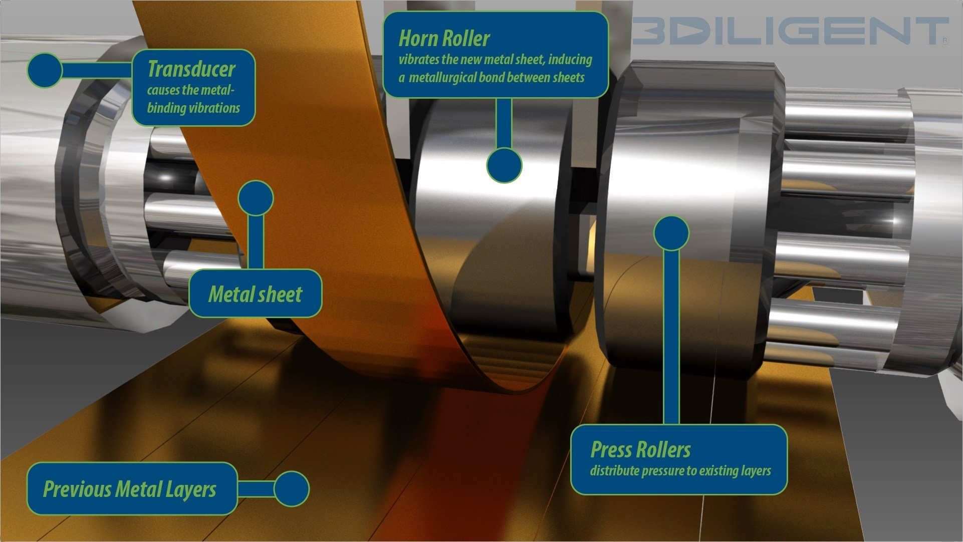
Ultrasonic Sheet Lamination is a low-temperature hybrid metal additive manufacturing process.
The technology works by welding thin metal foils together with ultrasonic vibrations under pressure. Oncethe printing process is complete, CNC milling is applied to remove any excess material and finish the part.
Since it is a low-temperature process, Ultrasonic Sheet Lamination does not melt the metal material. The process is also capable of fusing dissimilar metal types together.
The key advantages of this technique are its low cost, fast printing speeds and the ability to create parts with embedded electronics and sensors from a variety of metals.
New metal 3D printing processes
With the rapid evolution of metal 3D printing, hardware manufacturers are continually looking to develop new processes. Below, we’ve outlined a few newly-developed metal 3D printing technologies that have the potential to revolutionise metal 3D printing, both in terms of speed and cost.
Extrusion-based metal 3D printing
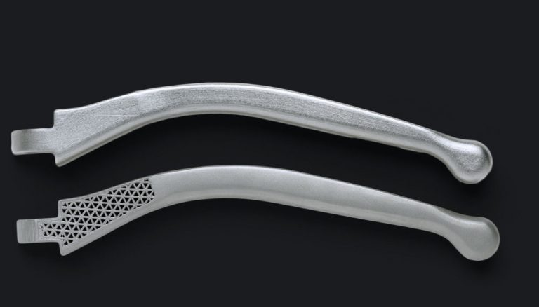
The two most prominent companies working in this area are Markforged and Desktop Metal. Both companies first unveiled their metal 3D printing systems, (Markforged’s Metal X and Desktop Metal’s Studio System) in 2017.
Extrusion-based metal 3D printing works similarly to Fused Deposition Modelling (FDM), where a filament is heated and extruded through a nozzle, creating a part layer by layer.
However, unlike the plastic filaments used in FDM, metal extrusion uses filaments made of metal powders or pellets encased in plastic binders.
Once a part has been printed, it remains in a ‘green state’ and will need to undergo additional post-processing steps: debinding to burn out the remaining plastic and sintering to fuse the metal particles together.
Extrusion-based metal 3D printing is one of the most affordable metal additive manufacturing processes. This is partly because it uses metal-injection-molding (MIM) materials, which are significantly less expensive than the metal powders used in powder-bed processes.
Material Jetting
Material Jetting is an inkjet printing process in which print heads are used to deposit photoreactive material in liquid form onto a build platform, layer by layer.
Material Jetting has typically been used as a prototyping technology to create highly accurate full-colour plastic models.
However, one company has recognised the potential of the technology for metal 3D printing: Israeli company, XJet, has developed a novel inkjetting technique for metals that can achieve a high level of detail and finish.
XJet’s NanoParticle Jetting™ (NPJ) technology uses print heads to deposit metal inks suspended in a liquid formulation. The process takes place in a heated chamber.
As the metal inks are deposited, they are deposited onto a hot building tray, evaporating the liquid formulation to leave only the metal particles. The particles have a small coating of bonding agent, allowing them to bond to each other in all three axes.
Once the print is complete, the part is then moved to an oven where it undergoes a sintering process. This technology can be used both for functional prototyping and on-demand manufacturing of small and medium-sized metal components.
Metal Jet (HP)
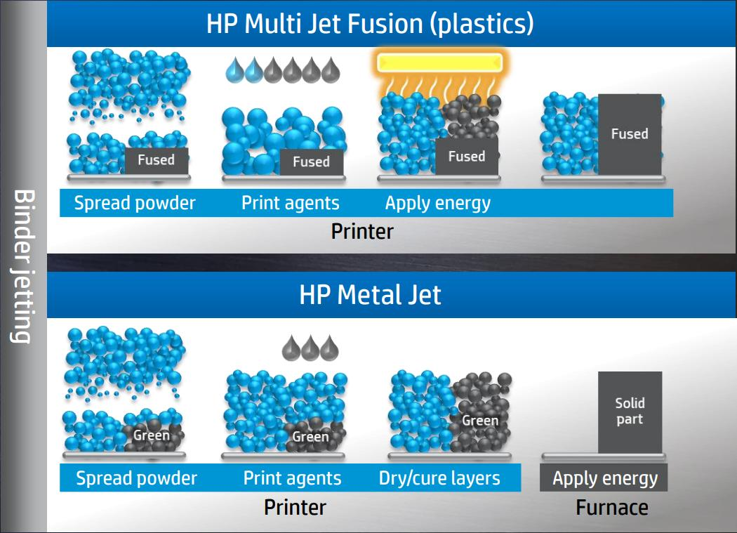
HP first made waves by moving into the 3D printing market in 2016, with the launch of its polymer Multi Jet Fusion system. In 2018, the company took its binder jetting technology one step further by announcing its new metal 3D printing system: Metal Jet.
The Metal Jet system is based on HP’s binder jetting process, which has been enhanced to enable faster and cheaper printing.
While it works similarly to other binder jetting machines, the system uses a proprietary binder developed with the help of HP’s Latex Ink technology. This new binder formulation is said to make it faster, lower-cost and much simpler to sinter a part.
Additionally, Metal Jet uses Metal Injection Moulding (MIM) powders and is capable of producing isotropic parts that meet ASTM standards.
One of the key features of the technology is the increased amount of printheads, which is said to make Metal Jet up to 50 times more productive than comparable binder and laser sintering machines on the market today.
Joule Printing (Digital Alloys)
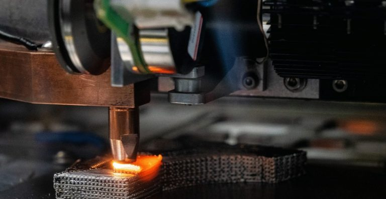
Joule Printing is a high-speed technology that uses metal wire as opposed to powder.
The metal wire is fed into a precision motion system with a precision wire feed. Once the wire is positioned, current is passed through the wire and subsequently into the print bed and the part itself. The metal wire is melted by the current as the print head moves, with the droplets of metal fused together to form the final part.
Joule Printing technology is said to enable the production of near net shape parts and can be used for tooling and other applications within the automotive, aerospace and consumer goods industries.
MELD (MELD Manufacturing)
MELD Manufacturing Corporation has developed a new, solid-state metal 3D printing process to manufacture metal parts. That it is solid-state means the process doesn’t require melting the metal material during the printing process.
Instead, the process involves passing metal material through a hollow rotating tool, where extreme pressure and friction work to deform the material that is being added, as well as the material that has already been deposited.
The process ensures that the parts produced have high strength and mechanical properties, such as corrosion resistance.
Parts printed with MELD technology are fully dense and don’t require subsequent heat treatment. Furthermore, the technology is not only well-suited for creating parts, but also for coating and repairing existing components.
Making the Business Case for Metal 3D Printing
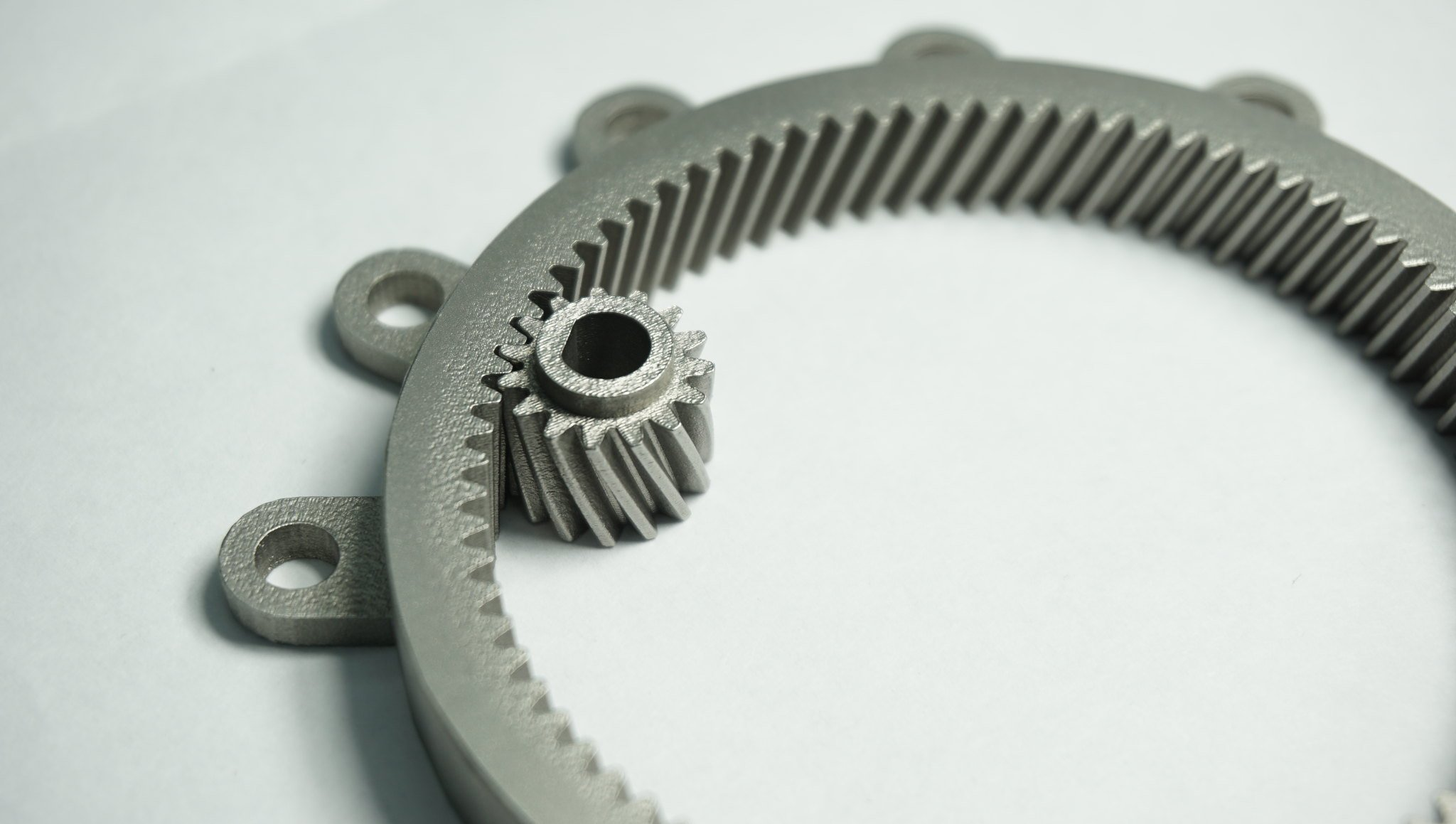
Metal 3D printing has the potential to transform the way parts are manufactured by providing a level of complexity and customisation that is not possible with traditional manufacturing processes.
When deciding whether to invest in metal 3D printing, it’s important to assess whether your company can benefit from the technology. Below, we’ve outlined some of the key benefits of metal 3D printing.
Save time and reduce costs
First, 3D printing removes the need for costly tooling and moulds, enabling manufacturers to eliminate expensive and time-consuming setup costs. Second, the ability to go from design to production can significantly slash lead times from weeks or months to days.
Finally, the ability to consolidate part assemblies with 3D printing can help to significantly save labour time and cost.
Waste less material
Traditional subtractive manufacturing methods involve extensive waste of material, with one study showing that the use of CNC milling machines to cut material from metal blocks can lead to material waste as high as 95%.
In comparison, metal 3D printing processes generate much less waste as material is sintered or melted only where necessary. In some cases, unsintered metal powders can even be reused.
As a result, material use with 3D printing is highly efficient, with material scrap rates being usually below 5 per cent.
Achieve greater design innovation
Metal 3D printing can be used to produce complex geometries, pushing the boundaries of what is possible with manufacturing. These complex designs can be produced more cost effectively than with traditional processes.
Coupled with design tools like topology optimisation and generative design, 3D printing can be used to create lightweight metal parts with enhanced functionality and mechanical properties.
These software design tools can therefore help to unlock a myriad of new, innovative design possibilities. For example, lattice structures can be factored into a design to reduce weight of a metal part and therefore improve the performance of a vehicle or aircraft.
Cost-effective low-volume production
With 3D printing, low-volume production becomes economically viable.
Due to high tooling costs, traditional manufacturing methods can be extremely expensive to implement for producing parts in low volumes.
In contrast, 3D printing doesn’t require tooling, and is therefore a more cost-effective option for low-volume production. One key example of this is in the case of customised parts, where products may need to be produced as a one-off or as part of a small batch.
3D printing can also be used to create parts on-demand. For example, companies can 3D print tools and spare parts in-house as they are needed — which both reduces the need to stockpile parts in a physical inventory and simplifies logistics and the overall supply chain.
Challenges of Metal 3D Printing
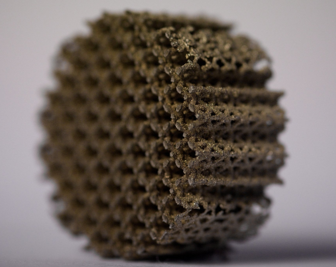
While the benefits of metal 3D printing are clear, there are challenges to successfully implementing the technology. Below, we cover some of the key challenges currently facing the metal 3D printing market.
High costs
Although the price of 3D printers has fallen significantly over the last decade, the cost of metal AM systems still remains one of the main challenges for companies looking to invest in the technology.
Currently, a metal 3D printer can easily cost into the hundreds of thousands of dollars and even upwards of $1 million.
At the same time, the current metal materials available on the market are generally quite limited, with costs being significantly higher than that of the metals used in traditional metal manufacturing.
That said, over the next few years, we expect that advances in metal materials science will both expand the choice of 3D printable metals and bring down costs.
Greater complexity
Multiple variables involved in metal 3D printing make it a far more complex process than polymer 3D printing. Currently, many companies lack the necessary expertise to successfully operate metal 3D printers in-house.
One possible way to get started with the technology is through collaboration with metal 3D printing service providers. Service bureaus can offer their expertise in choosing the right metal AM technology and materials.
For companies looking to bring the AM technology in-house, developing and implementing an AM strategy will be the key first step on this journey.
Ensuring part quality
Part quality and process repeatability are key concerns for manufacturers. When it comes to metal 3D printing, there is a wide range of variables that can affect the quality of a part. These variables span the whole AM workflow, from design to build preparation and post-processing.
However, controlling these variables to enable repeatable, high-quality metal parts remains a challenge.
The Materials
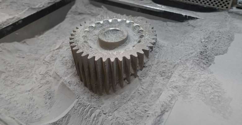
Metals have been the fastest-growing segment of the 3D printing materials market since 2012.
Metal 3D printing processes use high-quality metal materials. They are typically produced in powder form and must meet certain characteristics, like particle shape and size, and powder density.
Compared with traditional manufacturing process, the range of available 3D-printable metals remains limited.
This is due to the fact that specialised materials adapted or produced for metal 3D printing technologies can take years to develop.
However, some processes like DED can use metals originally developed for traditional processes, for example, in wire form.
Currently, the most commonly used materials for metal 3D printing include lightweight metals like aluminium, titanium and stainless steel.
However, the use of refractory metals and cobalt chrome alloys is also expanding, largely driven by applications in the aerospace and oil & gas industries.
In the table below, we’ve identified the more common metal 3D printing materials and their typical applications.
The Machines
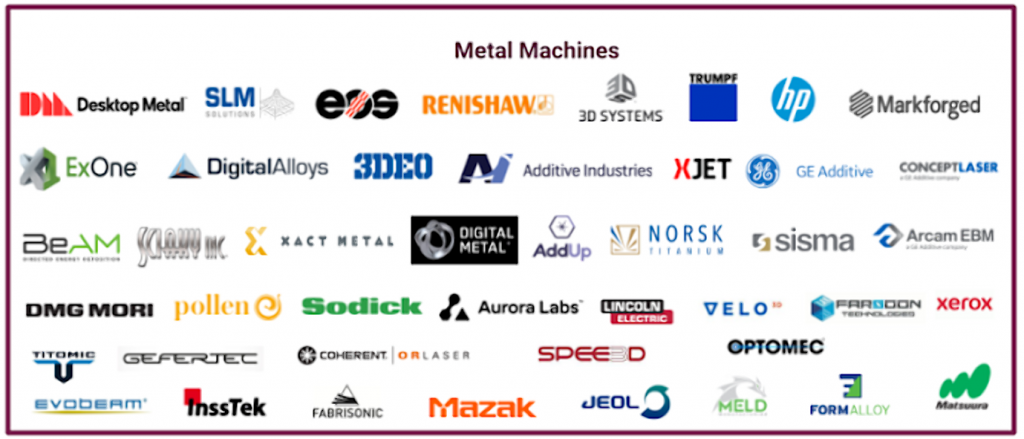
With metal 3D printing on the rise, the number of available metal 3D printers on the market is expanding.
According to the 2018 Wohlers Report, metal AM system sales grew by 80% in 2017, with an increase in the number of metal AM system manufacturers entering the market.
In the table available for download, we’ve summarised the main manufacturers of metal 3D printers, using powder-bed technologies, DED, Binder Jetting and extrusion-based metal 3D printing. While not an exhaustive list, it provides a high-level overview of the main machine manufacturers on the market.
| Technology | Manufacturer | System Name | Build Volume (mm) | Compatible materials |
|---|---|---|---|---|
| DMLS & SLM | 3D Systems | DMP Flex 100 | 100 x 100 x 80 mm | LaserForm 17-4PH (B), LaserForm CoCr (B) or (C) |
| DMLS & SLM | 3D Systems | ProX DMP 200 | 140 x 140 x 100 mm | LaserForm Ni625 (B) LaserForm 17-4PH (B) LaserForm Maraging Steel (B) LaserForm 316L (B) LaserForm CoCr (B) or (C) LaserForm AlSi12 (B) |
| DMLS & SLM | 3D Systems | ProX DMP 300 | 250 x 250 x 300 mm | LaserForm 17-4PH (B), LaserForm Maraging Steel (B), LaserForm CoCr (B) LaserForm AlSi12 (B) (Cobalt Chrome alloys, Stainless steel, Maraging Steel, Aluminium alloy (AlSi12)) |
| DMLS & SLM | 3D Systems | ProX DMP 320 | 275 x 275 x 380 mm | LaserForm Maraging Steel (A) LaserForm 17-4PH (A) LaserForm Ni625 (A) LaserForm AlSi10Mg (A) LaserForm CoCrF75 (A) LaserForm Ti Gr5 (A) LaserForm Ti Gr23 (A) LaserForm Ti Gr1 (A) LaserForm 316L (A) LaserForm Ni718 (A) (Titanium alloys, Aluminium, Nickel alloys, Stainless steel, Cobalt Chrome, Maraging Steel) |
| DMLS & SLM | 3D Systems | DMP Factory 500 Solution | 500 x 500 x 500mm | |
| DMLS & SLM | EOS | EOS M 100 | 100 mm x 95 mm | Cobalt Chrome Stainless Steel 316L Titanium Ti64 |
| DMLS & SLM | EOS | EOS M 290 | 250 x 250 x 325 mm | Aluminium Cobalt Chrome Maraging Steel Nickel Alloy Stainless Steel alloys Titanium and Titanium alloys |
| DMLS & SLM | EOS | EOS M 400 | 400 x 400 x 400 mm | Aluminium, Maraging Steel, Nickel Alloy, Titanium alloys |
| DMLS & SLM | EOS | EOS M 400-4 | 400 mm x 400 mm x 400 mm | Aluminium, Nickel Alloys, Maraging Steel, Stainless Steel, Titanium Ti64, Titanium Grade 2 |
| DMLS & SLM | EOS | EOSINT M 280 | 250 mm x 250 mm x 325 mm | EOS MaragingSteel MS1 EOS CobaltChrome MP1 EOS StainlessSteel GP1 EOS StainlessSteel PH1 EOS StainlessSteel 316L EOS Titanium Ti64 EOS Titanium Ti64ELI EOS Aluminum AlSi10Mg EOS NickelAlloy IN718 EOS NickelAlloy IN625 EOS NickelAlloy HX |
| DMLS & SLM | EOS | PRECIOUS M 080 | 80 x 80 x 95 mm | Gold, silver, platinum and palladium alloys |
| DMLS & SLM | Renishaw | RenAM250 | 250 mm x 250 mm x 300 mm | Ti6Al4V ELI AlSi10Mg Stainless steel 316L Tool steels Nickel alloys Cobalt chromium alloy. |
| DMLS & SLM | Renishaw | RenAM400 | 250 mm × 250 mm × 300 mm | Ti6Al4V ELI AlSi10Mg Stainless steel 316L Tool steels Nickel alloys Cobalt chromium alloy. |
| DMLS & SLM | Renishaw | RenAM 500M | 250 mm × 250 mm × 350 mm | Ti6Al4V ELI AlSi10Mg Stainless steel 316L Tool steels Nickel alloys Cobalt chromium alloy. |
| DMLS & SLM | Renishaw | RenAM 500Q | 250 mm x 250 mm x 350 mm | Ti6Al4V ELI AlSi10Mg Stainless steel 316L Tool steels Nickel alloys Cobalt chromium alloy. |
| DMLS & SLM | SLM Solutions | SLM 125 | 125 x 125 x 75 | Stainless Steel Tool Steel Cobalt-Chromium Inconel Aluminum Titanium |
| DMLS & SLM | SLM Solutions | SLM 280 2.0 | 280 x 280 x 350 | Stainless Steel Tool Steel, Cobalt-Chromium Super Alloys Aluminium Titanium |
| DMLS & SLM | SLM Solutions | SLM 500 | 500 x 280 x 325 | Aluminium alloys Stainless Steel Tool Steel Titanium Inconel Cobalt-Chrome |
| DMLS & SLM | Concept Laser (GE Additive) | Mlab cusing | 50 x 50 x 80 mm | Stainless steel Bronze Gold Silver alloy Cobalt-chromium alloy |
| DMLS & SLM | Concept Laser (GE Additive) | Mlab cusing R | 50 x 50 x 80 mm | Stainless steel Bronze Gold Silver alloy Cobalt-chromium alloy Titanium and titanium alloys |
| DMLS & SLM | Concept Laser (GE Additive) | Mlab cusing 200R | 100 x 100 x 100 mm | Stainless steel Aluminium Titanium alloy Commercially Pure Titanium Grade 2 Maraging steel Bronze Stainless steel, Nickel based alloy Cobalt-chromium alloy |
| DMLS & SLM | Concept Laser (GE Additive) | M1 cusing | 250 x 250 x 250 mm | Stainless steel Maraging tool steel, Stainless tool steel Nickel-based alloys Cobalt-chromium alloys |
| DMLS & SLM | Concept Laser (GE Additive) | M2 cusing | 250 x 250 x 350 mm | Stainless steel Aluminium alloys Titanium alloys Pure Titanium Grade 2 Maraging steel Corrosion resistant precipitation hardening steel Precipitation hardening stainless steel Nickel-based alloys Cobalt-chromium alloys |
| DMLS & SLM | Concept Laser (GE Additive) | M2 cusing Multilaser | 250 x 250 x 350 mm | Stainless steel Aluminium alloys Titanium alloys Pure Titanium Maraging steel Precipitation hardening steel Nickel-based alloys Cobalt-chromium alloys |
| DMLS & SLM | Concept Laser (GE Additive) | M LINE FACTORY | 500 x 500 x up to 400 mm | Aluminium alloys Titanium alloys Nickel-based alloy Cobalt-chromium alloy |
| DMLS & SLM | Concept Laser (GE Additive) | X LINE 2000R | 800 x 400 x 500 mm | Aluminium (AlSi10Mg) Titanium alloy (TiAl6V4) Nickel-based alloy |
| EBM | Arcam (GE Additive) | Arcam EBM A2X | 200x200x380 mm | TiAl, Nickel Alloy 718 |
| EBM | Arcam (GE Additive) | Arcam EBM Q10plus | 200 x 200 x 180mm | Titanium Ti6Al4V Cobalt-Chrome |
| EBM | Arcam (GE Additive) | Arcam EBM Q20plus | 350 x 380mm | Titanium Ti6Al4V Cobalt-Chrome |
| EBM | Arcam (GE Additive) | Arcam EBM Spectra H | 250 x 250 x 430mm | Titanium aluminide (TiAl) Alloy 718. |
| DMLS & SLM | Sisma | mysint100 | 100 mm x h100 mm | Cobalt Chrome Precious metals Bronze Steel alloys Nickel alloys Pure copper Copper alloys Titanium Aluminium alloys |
| DMLS & SLM | Sisma | mysint300 | 300 x 400 mm | Precious Metals Bronze Cobalt Chrome Stainless Steel Maraging Steel Nickel alloys Aluminium alloys Titanium |
| DMLS & SLM | DMG Mori | LASERTEC 30 SLM 2nd Gen. | 300 x 300 x 300mm | Aluminium Titanium Tool steel Cobalt-chrome Inconel |
| DMLS & SLM | Xact Metal | XM200C | 127 x 127 x 127 mm | Stainless Steel, Super Alloys, Cobalt Chrome, Hastelloy® X, Tooling Steels |
| DMLS & SLM | Xact Metal | XM200S | 127 x 127 x 127 mm | Aluminum Si10Mg, Bronze, Stainless Steel, Super Alloys, Cobalt Chrome, Hastelloy® X, Titanium Ti64, Tooling Steels |
| DMLS & SLM | Xact Metal | XM300C | 254 x 330 x 330 mm | Stainless Steel, Super Alloys, Cobalt Chrome, Hastelloy® X, Tooling Steels, Bronze |
| DMLS & SLM | AddUp | FormUp™ 350 | 350 x 350 x 350 mm | Stainless steels, Maraging steels, Nickel alloys, Titanium alloys, Aluminum alloys |
| DMLS & SLM | TRUMPF | TruPrint 1000 | 100 mm x 100 mm Height | Stainless steels, Tool steels, Aluminum, Nickel-based, Cobalt-chrome, Copper, Titanium, Precious metal alloys |
| DMLS & SLM | TRUMPF | TruPrint 3000 | 300 mm x 400 mm Height | Stainless steels, Tool steels, Aluminum, Nickel-based, Cobalt-chrome, Copper, Titanium, Precious metal alloys Bronze |
| DMLS & SLM | TRUMPF | TruPrint 5000 | 300 mm x 400 mm Height | Stainless steels, Tool steels, Aluminum, Nickel-based, Cobalt-chrome, Copper, Titanium, Precious metal alloys |
| DMLS & SLM | VELO3D | Sapphire | 315 mm diameter x 400 mm | Inconel 718, Titanium (6Al4V) |
| DED | Sciaky | EBAM® 68 | 711 x 635 x 1600 mm | Titanium Titanium alloys Inconel 718, 625, Tantalum, Tungsten, Niobium, Stainless Steels (300 series), Aluminum, Steel Zircalloy, Copper Nickel, Nickel Copper |
| DED | Sciaky | EBAM® 88 | 1219 x 89 x 1600 mm | Titanium Titanium alloys Inconel 718, 625, Tantalum, Tungsten, Niobium, Stainless Steels (300 series), Aluminum, Steel Zircalloy, Copper Nickel, Nickel Copper |
| DED | Sciaky | EBAM® 110 | 1778 x 1194 x 1600 mm | Titanium Titanium alloys Inconel 718, 625, Tantalum, Tungsten, Niobium, Stainless Steels (300 series), Aluminum, Steel Zircalloy, Copper Nickel, Nickel Copper |
| DED | Sciaky | EBAM®150 | 2794 x 1575 x 1575 mm | Titanium, Titanium alloys, Inconel 718, 625, Tantalum, Tungsten, Niobium, Stainless Steels (300 series), Aluminum, Steel Zircalloy, Copper Nickel, Nickel Copper |
| DED | Sciaky | EBAM® 300 | 5791 x 1219 mm x 1219 mm | Titanium, Titanium alloys, Inconel 718, 625, Tantalum, Tungsten, Niobium, Stainless Steels (300 series), Aluminum, Steel Zircalloy, Copper Nickel, Nickel Copper |
| DED | Optomec | LENS 450 | 100 x 100 x 100 mm | Titanium, Nickel, Tool Steel, Stainless Steel, Refractories, Composites, Cobalt, Aluminium, Copper |
| DED | Optomec | LENS MR-7 | 300 x 300 x 300 mm | Titanium, Nickel, Tool Steel, Stainless Steel, Refractories, Composites, Cobalt, Aluminium, Copper |
| DED | Optomec | LENS 850-R | 900 x 1500 x 900 mm | Titanium, Nickel, Tool Steel, Stainless Steel, Refractories, Composites, Cobalt, Aluminium, Copper |
| DED | Optomec | LENS 860 Hybrid | 860 x 600 x 610 mm | Titanium, Stainless Steel, Tool Steel, Inconel |
| DED | Optomec | LENS CS 600 | 600 x 400 x 400 mm | Inconel Alloys, Stainless Steels, Titanium Alloys |
| DED | Optomec | LENS CS 800 | 800 x 600 x 600 mm | Inconel Alloys, Stainless Steels, Titanium Alloys |
| DED | BeAM | Modulo 250 | 400 x 250 x 300 | Titanium Alloys, Steels, Nickel Alloys, Cobalt Alloys, and more |
| DED | BeAM | Modulo 400 | 650 x 400 x 400 | Titanium Alloys, Steels, Nickel Alloys, Cobalt Alloys, and more |
| DED | BeAM | Magic 800 | 1200 x 800 x 800 | Titanium Alloys, Steels, Nickel Alloys, Cobalt Alloys, and more |
| DED | InnsTek | MX-600 | 450 x 600 x 350 mm | Inconel, Steel |
| DED | InnsTek | MX-1000 | 1,000 x 800 x 650 mm | Inconel, Steel |
| DED | InnsTek | MX-Grande | 4,000 X 1,000 X 1,000 mm | Inconel, Steel |
| DED | DMG Mori | LASERTEC 65 3D | 735 x 650 x 560 mm | |
| Metal Binder Jetting | ExOne | M-Flex | 400 x 250 x 250 mm | Stainless steel, bronze, tungsten |
| Metal Binder Jetting | ExOne | M-Print | 800 x 500 x 400 mm | Stainless steel (420 and 316) |
| Metal Binder Jetting | ExOne | Innovent+ | 160 x 65 x 65 mm | Stainless steel |
| Metal Binder Jetting | ExOne | X1 25 PRO | 400 x 250 x 250 mm | Steel (136L, 304 L and 17-4PH), Stainless steels, Inconel 718 and 625, M2 and H11 tool steels, Cobalt chrome, Copper, Tungsten carbide cobalt |
| Metal Binder Jetting | Digital Metal | DM P2500 | 203 x 180 x 69 mm | Stainless steel (316L, 17-4PH), Titanium Ti6Al4V |
| Metal Binder Jetting | HP | Metal Jet | 430 x 320 x 200 mm | Stainless steel powders (developed for metal injection molding) |
| Metal Binder Jetting | Desktop Metal | Production System | 337 x 337 x 330 mm | Aluminium, titanium, high-performance alloys |
| Material Extrusion | Desktop Metal | Studio System | 300 x 200 x 200 mm | Alloy steel, Aluminium Carbide, Copper, Heavy alloy, High performance steel, Magnetics, Stainless steel, Super alloy, Titanium, Tool steel |
| Material Extrusion | Markforged | Metal X | 300 x 220 x 180 mm | Stainless Steel, Aluminum, Tool Steel, Inconel, Titanium |
Industrial Applications
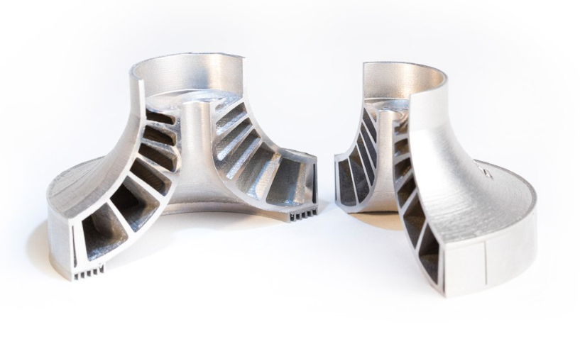
Metal 3D printing has found its niche in a number of industries, with players in the aerospace, automotive and medical industries at the forefront of driving innovation with the technology.
In this section, we take a look at the most common applications for the technology, as well as key use cases that have unlocked the benefits of metal 3D printing.
Aerospace
The aerospace industry has been a huge pioneer of metal 3D printing. By using the technology, aerospace companies hope to produce more efficient, lightweight aircraft parts to improve aircraft performance.
Within the aerospace industry, metal 3D printing is used in a range of applications, from functional prototypes to tooling, replacement parts and structural aircraft components.
General Electric
A great example is General Electric (GE), which is extensively using metal 3D printing to make and develop new products. GE’s subsidiary, GE Aviation, is producing fuel nozzles for the LEAP family of jet engines, with an aim to manufacture 100,000 fuel nozzles by 2020.
Having achieved the milestone of 30,000 3D-printed fuel nozzles in October 2018, GE looks like it’s well on its way to fulfilling this goal.
Using advanced design tools and Electron Beam Melting technology, GE’s engineers were able to create a fuel nozzle 25% lighter and 15% more fuel efficient than its traditionally produced counterpart.
The breakthrough in this case is that the fuel nozzle was printed as a single unit, whereas previous models incorporated 20 separate parts which needed to be subsequently assembled.
But GE has not stopped here. The company is also building its GE Catalyst, an advanced turboprop engine that has more than a third of its components 3D printed in various metals.
Similar to its fuel nozzles, the engineers behind the turboprop have achieved considerable part consolidation, reducing the number of parts produced from 855 to just 12. A redesign will also help to reduce the fuel burn of an engine by as much as 20%.
Automotive
Automakers have been using 3D printing since the technology’s early days — Ford Motor Company, for example, notably bought the third 3D printer ever made.
For many years, metal 3D printing has proved to be a cost-effective tool for prototyping and producing jigs and fixtures. However, advancements with the technology mean that more opportunities are opening up for end-part production.
Automotive companies can use metal 3D printing to create lightweight metal parts, leading to enhanced vehicle performance and lower fuel consumption. This is particularly beneficial for the motorsports industry, where 3D-printed car parts can offer racing teams significant performance advantages.
Another area of interest for the industry is also using 3D printing to produce spare parts that are typically produced in low volumes. 3D printing spare parts on demand enables automakers to receive parts at the point of need, reducing inventory costs and increasing agility.
BMW
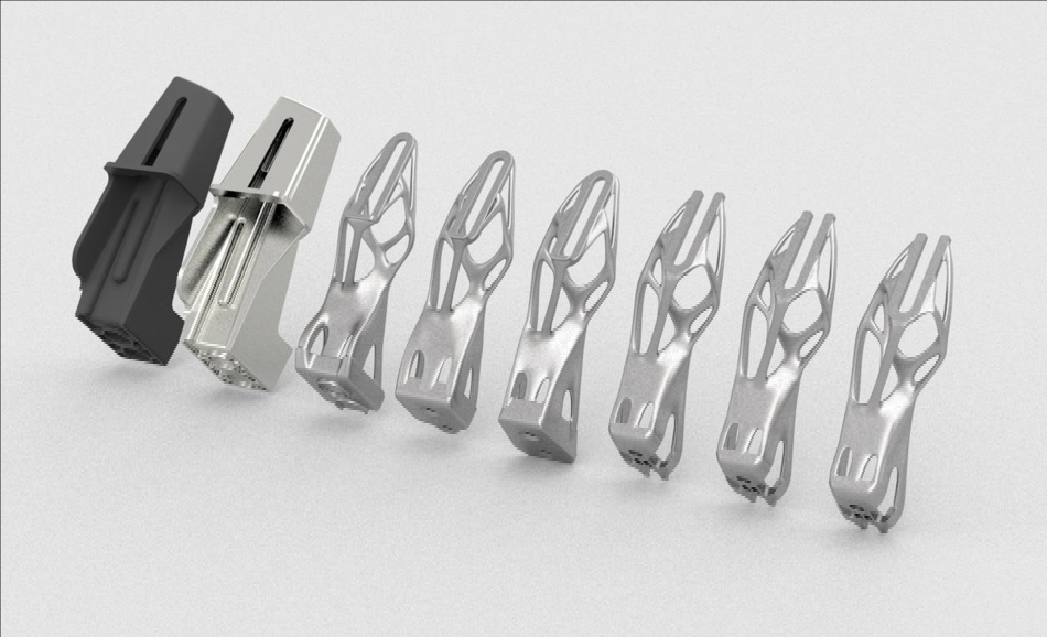
BMW is another company using 3D printing extensively. Most notably, the company has recently moved into the series production of a 3D-printed metal component for its 2018 BMW i8 Roadster vehicle.
Using topology optimisation, designers were able to optimise the vehicle’s roof bracket — a fixture for the folding/unfolding mechanism of the vehicle’s soft top. 3D printed in aluminium alloy powder (AlSi10Mg), the new roof bracket is 44% lighter than its conventionally made counterpart.
Furthermore, engineers optimised the design of the bracket to eliminate support structures. By doing so, the team was able to increase throughput from 51 to 238 of these parts per platform. This makes BMW’s roof bracket the first automotive component to be mass-produced with the help of metal 3D printing.
Bugatti
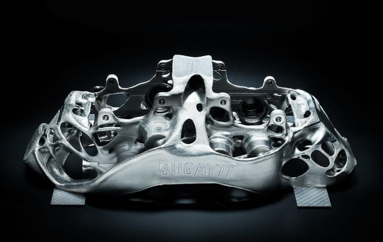
An exciting application of metal 3D printing comes from luxury car manufacturer, Bugatti. The French automaker has developed a 3D-printed brake caliper to be used on its Bugatti Chiron supercar.
An essential part of the braking system, the brake caliper has been made lighter and stronger thanks to 3D printing. Measuring 41 x 21 x 13.6 cm, the part took 45 hours to print using SLM technology and titanium powders.
By using 3D printing, Bugatti also achieved a 40% weight reduction for the caliper, when compared to machined aluminium alternative.
In 2018, the company successfully tested the brake caliper, proving that it can meet extreme strength, stiffness and temperature requirements.
Audi
Audi presents a different business case for metal 3D printing. In this case, the German automaker is using the technology to produce spare parts that are in low demand.
Metal 3D printing allows Audi to produce these parts on demand, producing and supplying spare parts as they are needed. This in turn greatly simplifies logistics and warehousing.
Audi identified that smaller, complex components would be most suited for metal 3D printing. A good example of a component is water adapters, which Audi is already producing for the Audi W12 engine. The company says that the load capacity of the components is comparable to that of parts manufactured using traditional methods.
Medical
In the medical field, metal 3D printing allows highly customised medical devices, like orthopedic implants, to be created.
It’s far from unusual for off-the-shelf orthopaedic implants to be used for replacement surgeries. However, prefabricated implants can sometimes cause problems after the surgery as they don’t always fit properly.
To avoid this, 3D printing is increasingly being used to create customised, patient-specific implants with improved functionality.
For example, implants can be designed with improved porosity and surface texture, facilitating the growth of the tissue around the implant. This level of complexity can only be achieved with 3D printing. SmarTech Publishing predicts that more than 2 million implants will be 3D printed in metal by 2025.
Additionally, metal 3D printing can be used to create hip and knee joint replacements, cranial reconstruction implants and spinal implants.
Lima Corporate
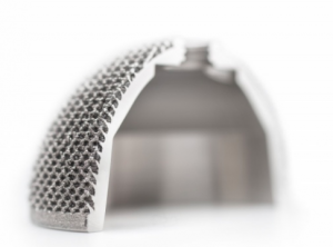
Italian medical device manufacturer Lima Corporate has been bringing additively manufactured hip implants to market for 10 years, using Electron Beam Melting (EBM) technology.
The company developed a technology for 3D printing biocompatible titanium in cellular solid structures that resemble natural bone. Such structures are used to coat an implant, allowing it to be better integrated with human tissue.
The technology is said to have helped almost 100,000 patients, enabling better implant performance and outcomes.
Industrial Goods
When it comes to the design and manufacture of tooling equipment, 3D printing can empower engineers to overcome traditional limitations. This can mean being able to create a mould or core in a matter of days instead of months, significantly reducing lead times.
Within the injection moulding industry, moulds are typically CNC-machined. Here, production costs can range from from $20,000 to hundreds of thousands of dollars. Lead times can last between 2 to 4 months. Additionally, moulds can often require multiple design iterations to achieve the final design, a costly and time-intensive process.
However, metal 3D printing can overcome these inefficiencies in several ways. First, the technology enables rapid design iterations, enabling changes to be made with relative ease.
Second, the performance of tooling aids and components can be enhanced with additive manufacturing.
For example, conformal cooling channels, lattice structures, and complex core/cavity shapes, which are too expensive or impossible to manufacture traditionally, can be factored into a mould design and 3D printed.
Conformal cooling channels are particularly beneficial as they help to achieve more homogenous heat transfer within the mould, compared to traditionally drilled straight-line cooling channels, resulting in greater cooling characteristics.
GW Plastics 3D prints moulds with conformal cooling
GW Plastics, US-based mould maker, has invested in hybrid metal 3D printing with the goal of building injection moulds with conformal cooling. One of the key reasons for this investment is faster cycles and better part quality enabled by 3D-printed moulds.
In fact, the company says 3D-printed moulds can save up to 30% of the cycle time by reducing cooling time. Furthermore, metal 3D printing allows GW Plastics to print a mould as a single piece, thus eliminating the need to assemble multiple components.
Post-processing
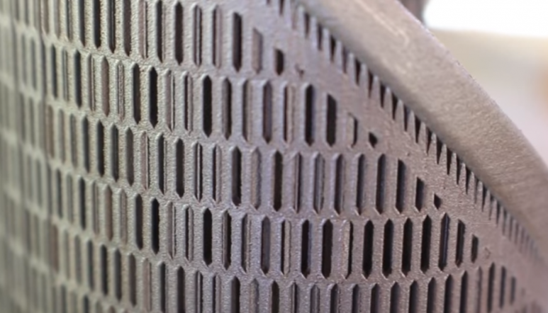
Post-processing is an unavoidable step when 3D printing metal parts. Post-processing helps to improve the mechanical properties, geometrical accuracy and aesthetics of a part, ensuring that a part meets the required design specifications.
Before printing your part, it’s important to understand the various post-processing methods that can be used to finish a metal part.
In this section, we’ll be looking at some of the main post-processing steps that can help to achieve the necessary finish for metal 3D-printed parts.
Stress relief
High temperatures and subsequent cooling are a common occurrence during the metal 3D printing process. However, when a metal part is subjected to such extreme temperature changes, this can lead to residual stress.
To avoid deformations that can occur as a result of a build-up of residual stress, parts produced with powder bed processes must undergo a stress relieving cycle. The number of stress relief cycles depends on the metal or alloy used to produce a part.
In order to protect the surface of a part from oxidation, the stress relieving heat treatment takes place in an inert (typically argon) atmosphere. Parts are typically heat treated while still attached to the build platform.
During the stress relieving cycle, the whole platform is placed in a furnace, where the part is heated to a temperature range between 550-675°C for 1 to 2 hours and then cooled down slowly. Stress corrosion cracking can also be reduced through this stress relief process.
Hot Isostatic Pressing (HIP)
Secondary heat treatment like Hot Isostatic Pressing (HIP) helps to improve the microstructure and mechanical properties of a metal part.
With HIP, high temperatures (up to 2200ºC) and isostatic inert gas pressure (from 100 to 3100 bar) are applied to a part to achieve the highest possible density, reduce porosity and eliminate internal voids.
The HIP treatment of metal parts results in optimum mechanical properties that can be compared with wrought and cast alloys.
Important to note is that the natural cooling in an HIP system can take between 8 and 12 hours. However, HIP systems powered by uniform rapid cooling technologies have been developed, allowing for the parts to be cooled from 1,260 to 300°C in less than 30 minutes.
Powder removal
With powder bed processes, a printed part is encapsulated in the unused powder which needs to be removed once the printing process is complete. The excess powder can be removed manually or automatically with the help of specialised equipment, and then recycled for later use.
The removal of any unmelted powder trapped inside a part should also be taken into consideration. For this reason, at least two escape holes should be factored into the design to help easily remove powder after printing.
Part removal
Once a part has been printed, it will need to be removed from the build platform. Build plates are then machined separately to remove excess material and return them to a usable state.
Wire Electrical Discharge Machining (WEDM) is the process of choice for cutting metal parts away from their build plates. WEDM involves creating electrical dischargers, releasing sparks which rapidly cut away material. Although the process is comparatively slow and used only with electrically conductive metals , it leaves a clean, smooth surface.
Cutting parts away with a bandsaw is another, considerably faster method. However, the process lacks the precision of wire EDM. However, if a part is going to be CNC machined afterwards, this precision can be sacrificed in favour of a faster post-processing time.
Support removal
Support structures are often considered a necessary evil when it comes to 3D printing, and this is particularly the case with metals.
Powder bed fusion technologies, like SLM and DMLS, will always require supports to ensure that they are anchored to the base plate and to mitigate the effects caused by residual stresses.
These supports are typically made from the same material as the part itself and help to minimise defects such as warping or cracking resulting from the high processing temperatures.
Supports are typically removed with the help of CNC machining. However, it’s a good practice to design as few supports as possible. In the Designing for Metal 3D printing section, we look at some of the ways to reduce the amount of support structures.
Surface finishing
As we’ve seen, a metal part that has just been printed won’t have the necessary properties required of the finished part. To achieve a smooth finish for a metal part, there are a number of common surface finishing techniques, including machining, sand blasting, media blasting and polishing.
For example, metal polishing can be used to achieve a ‘mirror-like’ finish for your part. Typically, polishing will be required before other surface treatments are conducted, in order to prevent corrosion and improve the appearance of the part. Applications are typically in the aerospace and automotive industries, as well as medical.
Abrasive blasting methods, such as sandblasting, bead blasting and media blasting, involves an abrasive material being forcibly sprayed onto a part to achieve a smooth surface.
Designing for Metal 3D Printing

Key Considerations
Metal additive manufacturing gives us the freedom and flexibility to produce parts with complex shapes and intricate features. However, as with any technology, it does have its own set of capabilities and limitations. Understanding the basics of design for metal 3D printing is therefore crucial to obtain a successful print.
Below are some of the key considerations to keep in mind when designing for metal 3D printing.
1. Wall Thickness
Choosing the right wall thickness can make the difference between a successful and a failed print.
As a general rule of thumb, it’s recommended to design walls with a minimum wall thickness of 0.4mm.
It’s also important to ensure that the wall thickness of your parts are not too thin or thick, as this can result in deformation during the printing process or cause damage after removal from the build plate.
In the case of thick walls, the mass can be minimised by applying lattice or honeycomb structures, making the overall printing process cheaper and faster.
2. Support structures
While it’s ideal to design a part with the minimum amount of supports necessary, support structures will virtually always be required with metal 3D printing technologies (except for DED).
Supports play two main roles: first, they are used to anchor a metal part to the base plate to draw away heat, which could otherwise cause residual stresses and build failures.
Second, supports are required to successfully print complex features such as holes, angles and overhangs. For these features, angle measures should be noted: overhangs with an angle less than 45° will require supports.
For features located inside a part, such as horizontal holes along the X or Y axis, it’s generally recommended to design angled support structures.
Angled supports can help maintain a solid connection with the printing bed while minimising the amount of contact the supports have with your part’s surface area. This will make post-processing much easier.
Finally, make sure to check that all support structures will be accessible after printing. Any supports that are difficult to reach will be hard to remove cleanly.
3. Overhangs and Self-Supporting Angles
Overhangs are unsupported downward-facing surfaces, and will need to be carefully considered when designing a part.
Large overhangs (typically over 1mm) will require support structures to prevent them from collapsing during the printing process. The maximum length of an unsupported horizontal overhang is typically 0.5mm, and it is important to keep your overhangs below this length.
If your design requires overhangs, you can also design fillets and chamfers under the downfacing surfaces to make the overhang self-supporting.
Angled features can be designed self-supporting. For this, the angle of a feature should not be less than 45°.
4. Part Orientation
Part orientation is another critical consideration with metal 3D printing. Experimenting with the orientation of your part is the best way to minimise the amount of support structures needed.
For example, if you want to make a metal part with hollow tubular features, a horizontal orientation will take up more space, while a vertical or angled orientation will save space and reduce the amount of supports needed.
Part orientation is also important in determining the accuracy and surface roughness of a part. When selecting your part orientation, keep in mind that downward and upward facing surfaces will have different surface roughness (so-called down-skins tend to have inferior surface finish). If you want to produce detailed features with the best accuracy, make sure to orientate these on the upward facing surface of the part.
5. Channels and Holes
Metal additive manufacturing is notable for its ability to produce parts with internal complex channels for improved fluid flow and holes. A general rule of thumb is to not design such features under 0.4mm in powder-bed processes and under 0.2mm in Metal Binder Jetting. Holes and tubes larger than 10mm in diameter will require support structures.
Keep in mind that perfectly round horizontal holes are still a challenge to 3D print. Consider redesigning such shapes into a self-supporting teardrop or diamond shape.
Additionally, if you are designing a hollow part, you need to factor in the design escape holes to ensure the removal of the unmelted powder. A recommended diameter for escape holes is 2-5mm.
Conclusion
Metal 3D printing: a viable manufacturing technology
Metal 3D printing is emerging as a viable manufacturing technology, as advancements across the spectrum of hardware, materials and software continue to be made.
The technology could help to drive new business models and product development strategies by enabling economic low-volume and on-demand production, innovative design possibilities and, of course, mass customisation.
Of course, it will take some time for companies to become fully confident with the technology. However, an increase in knowledge sharing and education will not only help to further the potential of metal 3D printing, but will also spur a wider adoption of the technology across industries.