A UV map is the flat representation of the surface of a 3D model used to easily wrap textures. The process of creating a UV map is called UV unwrapping.
The U and V refer to the horizontal and vertical axes of the 2D space, as X, Y, and Z are already being used in the 3D space.
Once the polygonal mesh has been created the next step is to “unwrap it” into a UV map. Now to give life to the mesh and make it look more realistic(or stylized) you want to add textures.
However, there is no such thing as a 3D texture, as they’re always based on a 2D image.
This is where UV mapping comes in, as it is the process of translating your 3D mesh into 2D information so that a 2D texture can be wrapped around it.
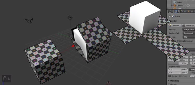
This may seem like a confusing idea at first, but it’s really very simple. If you’ve ever made a cube out of a cross of paper before, you have done the same process, only in reverse!
However, a cube is a basic example and as the meshes get more complex so do the UV maps. It can become quite a tedious process but it is essential to the 3D workflow.
Even if you don’t intend to texture a model, many modern real-time engines such as Unreal Engine 4 or Unity need your assets to be UV unwrapped to perform some of its light baking.
Exploring UV Unwrapping
Now that the basic concept of UV maps has been outlined we can dive into the more intermediate parts to UV unwrapping, namely seams.
Seams are an unfortunate and unavoidable side effect of flattening any 3D geometry.
A seam is a part of the mesh that had to be split to be able to convert the 3D mesh into a 2D UV map.
UV unwrapping is always a compromise of causing as little distortion to the wireframe as possible, while also keeping seams to a minimum.
Distortion in terms of a UV map is how much the shape and size of the polygons have had to change to accommodate the flattening process. Too much distortion will affect the way details are displayed on the final model.
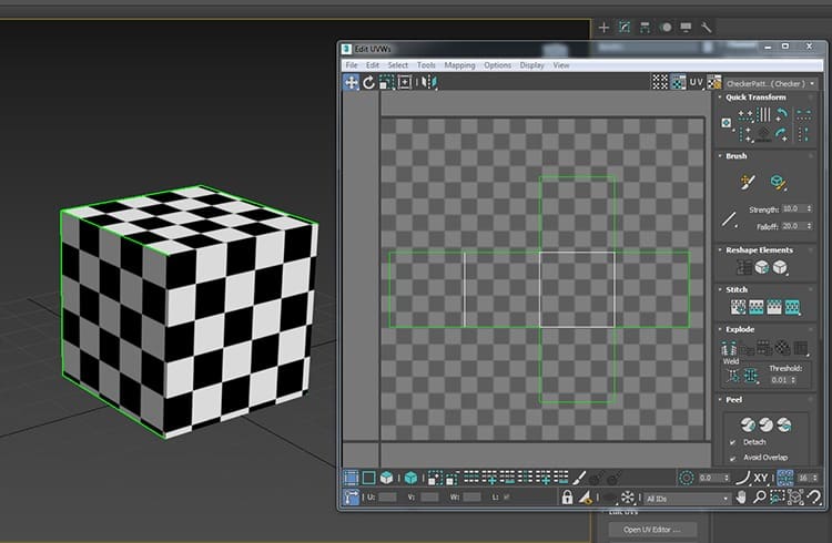
In this image, the way the cube has been unwrapped has caused no distortion to the polygons.
This is easy to tell by applying a basic chequered texture. If the chequered pattern isn’t stretched then you’ve avoided distortion in your unwrap.
However, the downside to this method of just splitting all your polygons apart is the number of seams it produces.
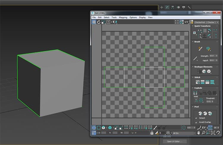
The cube on the left has the UV seams highlighted in green. You can see the pattern doesn’t line up as it moves around the edges. This can become a problem in more complex meshes so you need to practice and get smart with your seam placement.
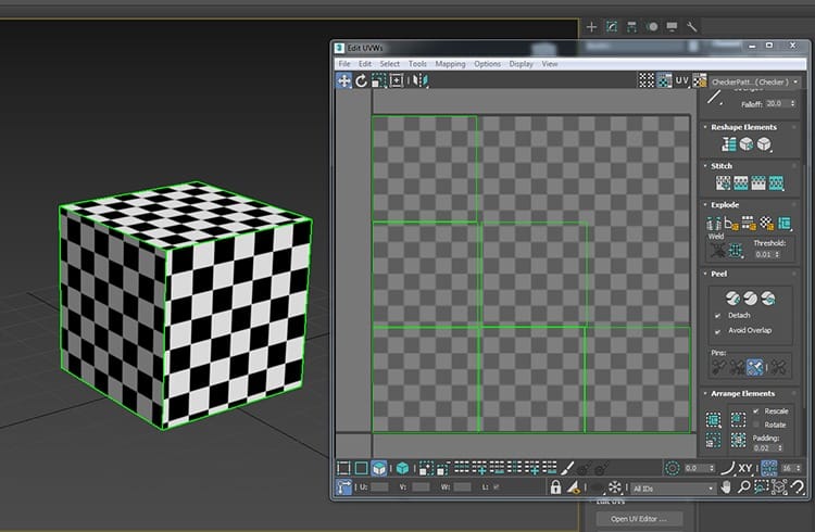
This is an example of what happens if you heavily distort your polygons in your UV unwrap. The texture on this cube is no different than the previous example but as you can see it has been stretched and pulled out of shape.
However the lack of seams does mean that the pattern lines up and follows around the edges of the cube, but the payoff is not worth the sacrifice in this instance.
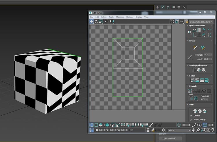
The obvious answer to this is to find a balance between the two.
In this image, you can see that the chequered pattern is preserved and we have some nice continuous edges that flow around the front of the cube.
As you practice and do more unwrapping you learn where the best places to “hide” your seams are to make them less noticeable.
Good rules for seams to make them less obvious are:
- Make them follow hard edges where they are usually less noticeable
- Hide them behind other parts of the model. For example, if unwrapping a head place your seams under where the hair will be.
- Hide them underneath or behind the focal point of your model, where people are less likely to see them.
Another thing to consider when unwrapping your 3D mesh is overlapping UVs.
Overlapping UVs are when you have two or more of the polygons in your UV map on top of one another. This means that these two parts of your model will display the same information of the texture as they both occupy the same UV space.
Overlapping UVs are usually something you want to avoid so you can keep your texture varied and not accidentally end up with your texture looking incorrect. That said there are times where you may intentionally use overlapping UVs. If a texture is quite basic then you may have multiple parts of your mesh over the same UV space to repeat the texture.
This technique can be very useful as it allows you to keep your texture sizes down which means if you are using a game engine it will generally run smoother.
This is even more important when developing for weaker machines like mobile phones.
One final thing to know about UV maps is UV channels.
UV channels allow the same object to have multiple UV maps. This is again very important for game engines.
As mentioned earlier in the article, game engines use UV maps to bake in lighting information.
This means that there can be absolutely no overlapping UVs as shadow information will get put in the wrong areas of the model and you will usually get some sort of error message.
Now overlapping UVs are sometimes a good idea within game development as I mentioned.
So the compromise is to have 2 UV channels. One with UV information for your textures and a second with UV information for your lighting. It gets easier the more you do it but there is a lot of detail to the UV mapping process.
Hopefully, you have a better understanding of UV mapping by now. It’s a simple enough process that can seem daunting at first, but quite easy to get the hang of with practice.