In this section, we answer these questions and show you common examples of injection molded parts to help you familiarize yourself with the basic mechanics and applications of the technology.
From rapid prototyping to end production, get your parts manufactured with lower cost, higher quality, and faster global delivery. FacFox offers professional manufacturing services including 3D printing, CNC machining, injection molding, urethane casting, metal casting, and more. You could find what you need at FacFox.
What is injection molding?
Injection molding is a manufacturing technology for the mass-production of identical plastic parts with good tolerances. In Injection Molding, polymer granules are first melted and then injected under pressure into a mold, where the liquid plastic cools and solidifies. The materials used in Injection Molding are thermoplastic polymers that can be colored or filled with other additives.
Almost every plastic part around you was manufactured using injection molding: from car parts, to electronic enclosures, and to kitchen appliances.
Injection molding is so popular, because of the dramatically low cost per unit when manufacturing high volumes. Injection molding offers high repeatability and good design flexibility. The main restrictions on Injection Molding usually come down to economics, as a high initial investment for the is required. Also, the turn-around time from design to production is slow (at least 4 weeks).
The injection molding process
Injection molding is widely used today for both consumer products and engineering applications. Almost every plastic item around you was manufactured using injection molding. This is because the technology can produce identical parts at very high volumes (typically, 1,000 to 100,000+ units) at a very low cost per part (typically, at $1-5 per unit).
But compared to other technologies, the start-up costs of injection molding are relatively high, mainly because custom tooling is needed. A mold can cost anywhere between $3,000 and $100,000+, depending on its complexity, material (aluminum or steel), and accuracy (prototype, pilot-run, or full-scale production mold).
All thermoplastic materials can be injection molded. Some types of silicone and other thermoset resins are also compatible with the injection molding process. The most commonly used materials in injection molding are:
- Polypropylene (PP): ~38% of global production
- ABS: ~27% of global production
- Polyethylene (PE): ~15% of global production
- Polystyrene (PS): ~8% of global production
Even if we take into account all other possible manufacturing technologies, injection molding with these four materials alone accounts for more than 40% of all plastic parts produced globally every year!
Injection molding machines: how do they work?
An injection molding machine consists of 3 main parts: the injection unit, the mold – the heart of the whole process – and the clamping/ejector unit.
In this section, we examine the purpose of each of these systems and how their basic operation mechanics affect the end-result of the Injection molding process.
Watch a large injection molding machine in action while producing 72 bottle caps every 3 seconds in the video here:
The injection unit
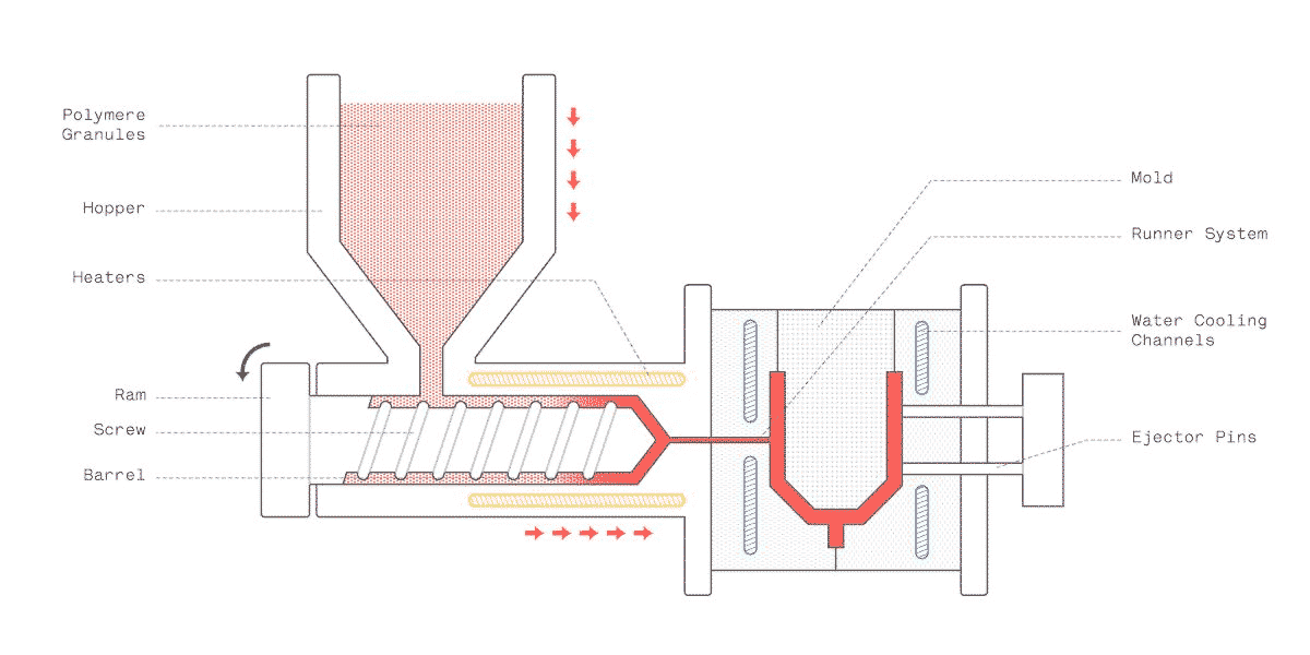
The purpose of the injection unit is to melt the raw plastic and guide it into the mold. It consists of the hopper, the barrel, and the reciprocating screw.
Here is how the injection molding process works:
- The polymer granules are first dried and placed in the hopper, where they are mixed with the coloring pigment or the other reinforcing additives.
- The granules are fed into the barrel, where they are simultaneously heated, mixed, and moved towards the mold by a variable pitch screw. The geometry of the screw and the barrel are optimized to help build up the pressure to the correct levels and melt the material.
- The ram then moves forwards and the melted plastic is injected into the mold through the runner system, where it fills the whole cavity. As the material cools down, it re-solidifies and takes the shape of the mold.
- Finally, the mold opens and the now solid part is pushed out by the ejector pins. The mold then closes and the process repeats.
The whole process can be repeated very fast: the cycle takes approximately 30 to 90 seconds depending on the size of the part.
After the part is ejected, it is dispensed on a conveyor belt or in a holding container. Usually, injection molded parts are ready to use right away and require little to no post-processing.
Manufacturing the mold
The mold is like the negative of a photograph: its geometry and surface texture is directly transferred onto the injection molded part.
It usually makes up the largest portion of the start-up costs in injection molding: the cost of a typical mold starts at approximately $2,000-5,000 for simple geometry and relatively small production runs (1,000 to 10,000 units) and can go upwards to $100,000 for molds optimized for full-scale production (100,000 units or more).
This is due to the high level of expertise required to design and manufacture a high-quality mold that can produce accurately thousands (or hundreds of thousands) of parts.
Molds are usually CNC machined out of aluminum or tool steel and then finished to the required standard. Apart from the negative of the part, they also have other features, like the runner system that facilitates the flow of the material into the mold, and internal water cooling channels that aid and speed up the cooling of the part.
Recent advances in 3D printing materials have enabled the manufacturing of molds suitable for low-run injection molding (100 parts or less) at a fraction of the cost. Such small volumes were economically unviable in the past, due to the very high cost of traditional mold making.
The anatomy of the mold
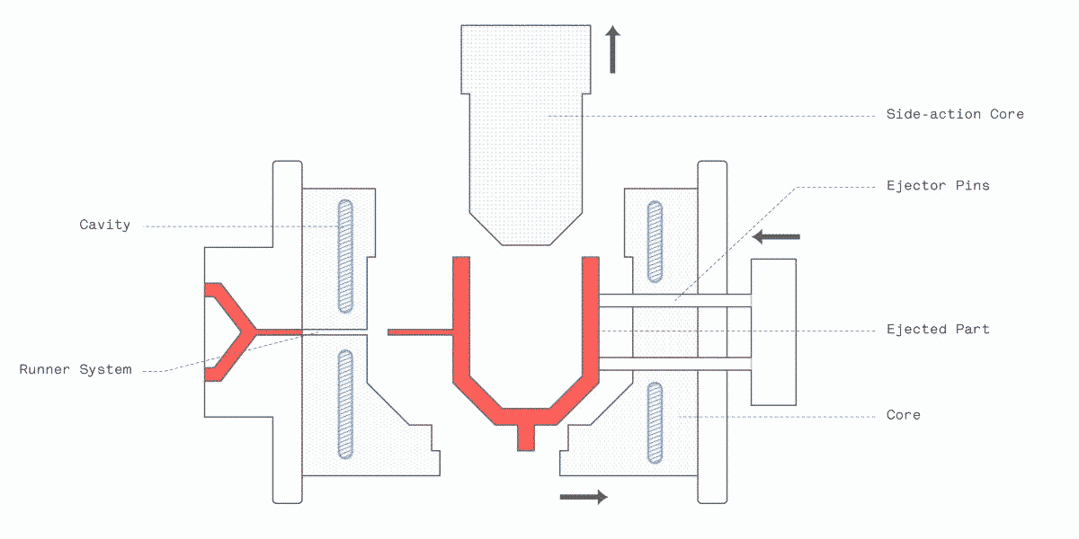
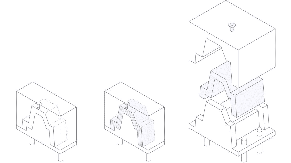
The simplest mold is the straight-pull mold. It consists of 2 halves: the cavity (the front side) and the core (the backside).
In most cases, straight-pull molds are preferred, as they are simple to design and manufacture, keeping the total cost relatively low. There are some design restrictions though: the part must have a 2D geometry on each side and no overhangs (i.e. areas that are not supported from below).
If more complex geometries are required, then retractable side-action cores or other inserts are required.
Side-action cores are moving elements that enter the mold from the top or the bottom and are used to manufacture parts with overhangs (for example, a cavity or a hole). Side-actions should be used sparingly though, as the cost increases rapidly.
Interesting fact: About 50% of the typical injection molding cycle is dedicated to cooling and solidification. Minimizing the thickness of design is key to speed up this step and cuts costs.
The 2 sides of the mold: A side & B side
Injection-molded parts have two sides: the A side, which faces the cavity (front half of the mold), and the B side, which faces the core (back half of the mold). These two sides usually serve different purposes:
- The A side usually has a better visual appearance and is often called the cosmetic side. The faces on the A side will be smooth or will have a textured according to your design specifications.
- The B side usually contains the hidden (but very important) structural elements of the part (the bosses, ribs, snap-fits, and so on). For this reason it is called the functional side. The B side will often have a rougher finish and visible marks from the ejector pins.
Injecting material into the mold: The runner system
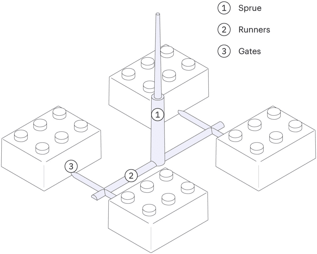
The runner system is the channel that guides the melted plastic into the cavity of the mold. It controls the flow and pressure with which the liquid plastic is injected into the cavity and it is removed after ejection (it snaps off). The runner system usually consists of 3 main sections:
- The sprue is the main channel in which all the melted plastic initially flows through as it enters the mold.
- The runner spreads the melted plastic along the face where the two halves of the mold meet and connect the spur to the gates. There may be one or more runners, guiding the material towards one or multiple parts. The runner system is cut off from the part after ejection. This is the only material waste in injection molding, 15-30% of which can be recycled and reused.
- The gate (is the entry point of the material into the cavity of the mold. Its geometry and location are important, as it determines the flow of the plastic.
Different gates types are suitable for different applications. There are 4 types of gates used in injection molding:
- Edge gates inject material at the parting line of the two halves of the mold and are the most common gate type. The runner system has to be removed manually later, leaving a small imperfection at the injection point.
- Tunnel gates inject material below the parting line. The runner system snaps off as the part is ejected from the mold, eliminating the need for manual removal. This makes this type of gate ideal for very large volumes.
- Post gates inject the material from the backside of the cavity, hiding the small imperfection left from breaking the other gate types. These gates are used for parts that require an excellent visual appearance.
- Hot tips are directly connected to the spur and inject plastic from the top side of the part. No material is wasted this way on the runner system making them ideal for large scale production, but a dimple will be visible at the injection point.
The vestige
At the point where the runner system connected with the part, a small imperfection is usually visible, called the vestige.
If the presence of the vestige is not desirable for aesthetic purposes, then it can also be “hidden” in the functional B-side of the part.
The clamping and ejection system
On the far side of an injection molding machine is the clamping system. The clamping system has a dual purpose: it keeps the 2 parts of the mold tightly shut during injection and it pushes the part out of the mold after it opens.
After the part is ejected, it falls onto a conveyor belt or a bucket for storage and the cycle starts over again.
Alignment of the different moving parts of the mold is never perfect though. This causes the creation of 2 common imperfections that are visible on almost every injection molded part:
- Parting lines which are visible on the side of a part where the 2 halves of the mold meet. They are caused by tiny misalignments and the slightly rounded edges of the mold.
- Ejector (or witness) marks which are visible on the hidden B-side of the part. They are created because the ejector pins are slightly protruding above or indented below the surface of the mold.
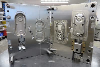
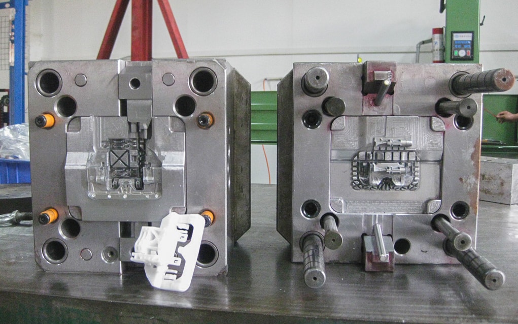
The image below shows the mold used to manufacture both sides of the casing for a remote controller. Quick quiz: try to locate the core (A-side), the cavity (B-side), the runner system, the ejector pins, the side-action core, and the air vents on this mold.