Without finite element analysis, you wouldn’t have many of the products around you today.
Finite Element Analysis or FEA is the simulation of a physical phenomenon using a numerical mathematic technique referred to as the Finite Element Method, or FEM. This process is at the core of mechanical engineering, as well as a variety of other disciplines. It also is one of the key principles used in the development of simulation software. Engineers can use these FEM to reduce the number of physical prototypes and run virtual experiments to optimize their designs.
Complex mathematics is required in order to understand the physical phenomena that occur all around us. These include things like fluid dynamics, wave propagation, and thermal analysis.
Analyzing most of these phenomena can be done using partial differential equations, but in complex situations where multiple highly variable equations are needed, Finite Element Analysis is the leading mathematical technique.
The history of finite element analysis
The beginnings of FEA date back to the famous mathematician Euler, in the 16th century. However, a more rigid definition of “FEA” traces the first mention of the method back to the works of Schellbach in 1851.
Finite Element Analysis was a process developed for engineers by engineers as a means to address structural mechanics problems in civil engineering and in aerospace.
This practical intention of the methodology meant that from the beginning, these methods were designed as more than just mathematical theory. By the mid-1950s, the techniques of FEA had become advanced enough that engineers could start using it in real-world situations.
The mathematical principles of FEA are also useful in other areas, such as computational fluid dynamics or CFD. The key difference here is that FEA focuses on structural analysis and CFD on fluid dynamics.
What does running FEA entail?
Essentially, FEA algorithms are integrated into simulation software like Autodesk Inventor Nastran or ANSYS’s suite of software.
These programs are usually integrated into computer-aided design (CAD) software, making it much easier for engineers to go from design to running complex structural analysis.
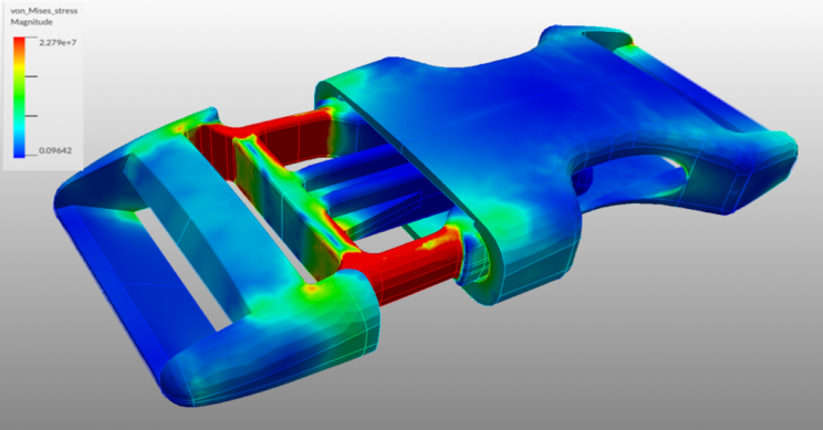
To run an FEA simulation, a mesh is first generated, containing millions of small elements that make up the overall shape. This is a way of transcribing a 3D object into a series of mathematical points that can then be analyzed. The density of this mesh can be altered based upon how complex or simple a simulation is needed.
Calculations are run for every single element or point of the mesh and then combined to make up the overall final result for the structure.
Since the calculations are done on a mesh, rather than the entirety of a physical object, it means that some interpolation needs to occur between the points. These approximations are usually within the bounds of what’s needed. The points of the mesh where the data is known mathematically are referred to as nodal points and tend to be grouped around boundaries or other areas of change in an object’s design.
FEA can also be applied to thermal analysis within a material or shape.
For example, if you know the temperature at one point in an object, how would you determine the exact temperature at other points of the object, dependent upon time? Utilizing FEA, an approximation can be made for these points using different modes of accuracy. There’s a square approximation, a polynomial approximation, and a discrete approximation. Each of these techniques increases in accuracy and complexity.
If you’re really interested in the intense mathematical side of FEA, take a look at this post from SimScale that goes into the nitty-gritty.
Computational fluid dynamics
The other type of FEA that we mentioned earlier is Computational Fluid Dynamics, which warrants a look into how it’s used.
The core of CFD is based on the Navier-Stokes equations, which examine single-phase fluid flows. In the early 1930s, scientists and engineers were already using these equations to solve fluid problems, but due to the lack of computing power, the equations were simplified and reduced to 2 dimensions.
While rudimentary, these first practical applications of fluid dynamic analysis gave way to what would soon be an essential simulation asset.
For most of the early years, solving CFD problems entailed simplifying equations to the point that they could be done by hand. By no means was the average engineer using these calculations; rather, up until the late 1950s, CFD remained a largely theoretical and exploratory practice. As you could probably have guessed, computing technology improved in the 1950s, allowing the development of algorithms for practical CFD.
The first functional CFD computer simulation model was developed by a team at the Los Alamos National Lab in 1957. The team spent the better part of 10 years working on these computational methods, which created the early models for much of the foundation of modern programs, spanning the vorticity-in-stream function to particle-in-cell analysis.
By 1967, Douglas Aircraft had developed a working, 3-dimensional CFD analysis method. The analysis was fairly basic and was developed for fluid flow over airfoils. It later became known as the ‘panel method,’ as the geometry being analyzed was largely simplified to make computation easier.
From this point onward, the history of CFD is largely based on innovations in mathematics and computer programming.
Full potential equations were incorporated into the methodology by Boeing in the 1970s. The Euler equations for transonic flows were incorporated into codes in 1981. While the early history of CFD is ripe with development, the companies involved in pursuing the technology were also notable. The two key players in advancing computations techniques for CFD were NASA and Boeing.
By the 1990s, however, the technology and computing ability had become advanced enough that automakers also began seeing the application of CFD in automotive design. GM and Ford adopted the technology in 1995 and began making cars that were much more aerodynamic when compared to the boxy wagons of the past.
The history of CFD is riddled with big names in the industry, all of which have developed CFD analysis into one of the biggest simulation tools available.
For many modern engineers, understanding the complex mathematics behind CFD isn’t necessary to run simulations. The tools are not only being used by experts in fluid dynamics and mathematics, but they can also now be accessed by the everyday engineer having virtually any skill level.
I don’t know about you, but having access to some of the most mathematically powerful simulation analysis software as just a common engineer is, well, pretty cool.
Together, FEA and CFD algorithms built-in to modern CAD tools give engineers access to what are essentially mathematical superpowers.