Walls are an important part of any 3D print. Learn how to find the perfect wall thickness for your 3D prints!
Shells in a Nutshell
In traditional manufacturing, parts are a single full or hollow body, with no distinction between the interior and exterior areas of the model. In contrast, the interior and exterior of 3D printed parts are technically separate because the machine prints the two areas in completely different ways.
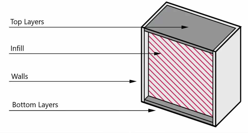
The inside portion of a 3D print is the infill, while the exterior is referred to as the shell. The infill can be printed in any density between 0% (hollow) and solid (100%) as well as in a variety of specific structures. The shell, however, is printed completely solid.
The shell isn’t only the most noticeable element of a 3D print, but it also heavily influences the model’s mechanical properties (e.g. strength). It comprises the walls and the top and bottom layers of a print. The former constitutes the vertical exterior regions, spanning a print’s height, and the top and bottom layers cover the horizontal regions.
These two regions are distinct because the walls cover the horizontal perimeter of a print and continue upwards along the Z-axis. The top and bottom layers cover the entire horizontal area within the perimeter established by the walls.
Shells and their sub-components are vital parts of any 3D print because, as we said, they can affect a part’s strength and durability. That’s why it’s critical to ensure that your shell slicer settings align with the purpose of your 3D printed part.
In this guide, we’ll discuss the most important shell settings, including those for walls and top and bottom layers. In addition, we’ll go over how to use these settings correctly and some other relevant information.
The Main Settings
Almost all 3D slicer programs, which turn a 3D model into 3D printable G-code, have shell settings. Before we get started, though, it’s important to note that most of our terminology in this article is based on Cura. The terms used in other 3D slicers should be obvious, though. For example, in Slic3r and PrusaSlicer, shells are referred to as “Perimeters”.
These settings can make or break a print because, if set incorrectly, your object will most definitely contain visual imperfections. Many different settings affect how shells are printed in one way or another, but there are a couple of super important ones.
Thickness, Line Count, & Layers
Perhaps the most important setting for walls and top and bottom layers is the thickness of the shell features. Unfortunately, there’s no one slicer setting for shell thickness most of the time, as it’s usually split into wall thickness and top and bottom layer thickness.
Moreover, shell thickness settings usually can be approached as either line count or width/height (in millimeters). These two ways of approaching shell thickness are directly correlated with each other; adjusting one will automatically adjust the other. So, you can work with whichever you feel more comfortable with.
Wall width in millimeters, called simply “Wall Thickness” in Cura, determines the width of the set of walls on a print. In terms of the other approach, the wall line count setting represents the desired number of passes the nozzle should take for the walls.
The thickness settings are very similar for the top and bottom layers. Top and bottom thickness refers to the height of the layers. You have the option of either adjusting them in a single setting or separately.
The top and bottom layers settings define the line count. Keep in mind, however, that if you go this route, the actual height of these layers will depend on what you’ve set for the overall print’s layer height.
The shell thickness or line count value should change based on the purpose of your model and the material you’re printing; there’s no one-size-fits-all approach. The more walls you have, the longer your print will take and the more material your machine will consume. Your part is also likely to be stronger.
Recommendations
Now that you know all about shell thickness settings, it’s time to set your wall thickness (or line count) and top and bottom thickness (or layers) in your slicer. Common values for printing regular, moderately strong parts include a wall thickness of 0.8-1.6 mm (3-4 wall lines) and a top and bottom thickness around 0.8-1.2 mm (4-6 layers depending on the layer height set). For most cases, your slicer’s default values will be suitable.
If you want to make your own custom values, though, there are a few rules of thumb you might want to know about:
- We suggest using a multiple of your nozzle diameter for the wall thickness because it’s ideal for printing full-size walls.
- Similarly, we recommend using a multiple of your layer height for the top and bottom thickness as full-size layers yield the best results.
- If you want higher-strength parts, use larger values such as a wall thickness of 2-3 mm and a top and bottom thickness of 1.6-2 mm.
- For more display-oriented models that don’t need much strength, you can get away with a 0.4-mm wall thickness and a top and bottom thickness of 0.2-0.8 mm.
Special Applications
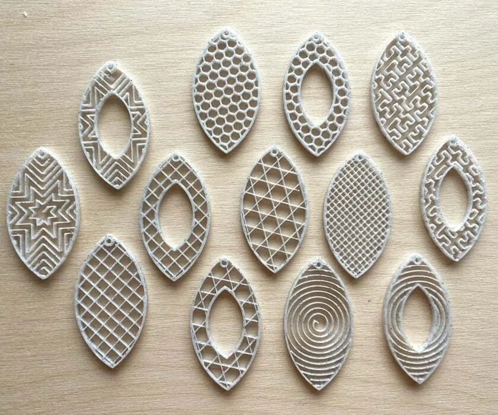
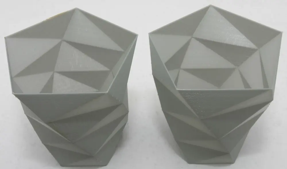
There are also some special ways you can use shell thicknesses, such as using zero top and bottom layers to expose an infill pattern. This is common, for example, in jewelry or phone cases.
Another example is thicker shells and no infill for functional parts involving frames or rod-like structures. In a model like this phone stand, for example, all of the cross dimensions are small enough that thicker shells can replace the need for infill.
Depending on how a part is designed, shells can provide greater part strength than the equivalent amount of infill material. It might also result in added flexibility.
Other Settings
Now that you know the ins and outs of shell thickness, it’s helpful to get to know a few other important settings. These allow you to fine-tune your model’s shells to prevent visual and mechanical imperfections.
Infill Overlap Percentage
This setting refers to the overlap between the infill lines and the walls. The value you enter for this setting is a percentage of the infill line width. The larger the value, the tighter the bond between the walls and the inside of the print.
The default value for this setting is 30% in Cura. You may want to add 10% to this value to increase your model’s strength. Conversely, you could subtract 10% to conserve material and speed up your print time.
Speed
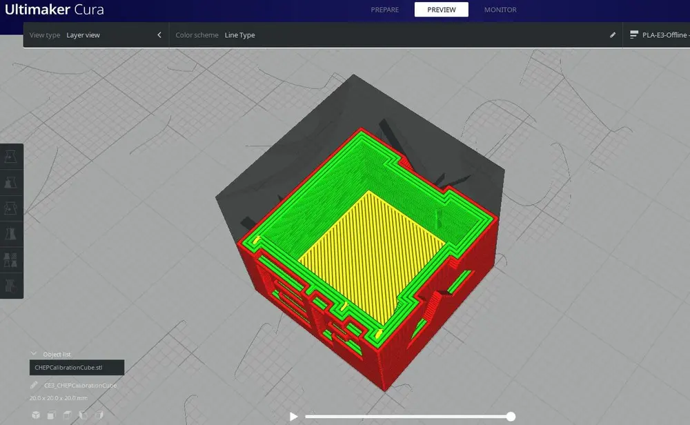
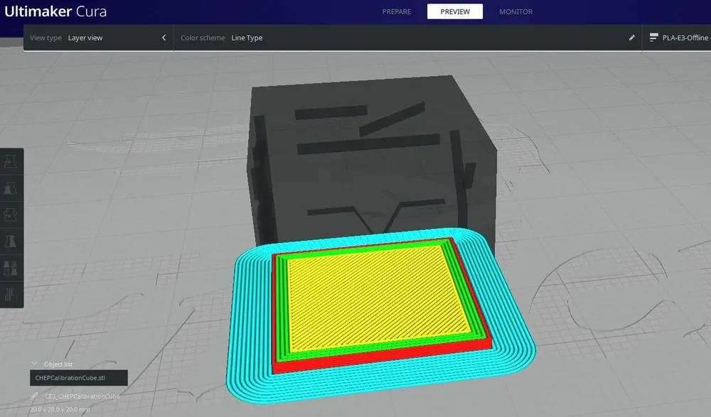
Another important consideration is print speed, specifically the speeds for the inner wall, outer wall, and the top and bottom layers. These settings determine how fast the stated elements of a print are printed, and they can affect the print quality of the underlying area. It’s important to mention that the inner wall is simply the wall adjacent to the infill (the innermost wall), and the outer wall is the visible outermost wall.
The Cura default values are 30 mm/s for both wall speeds as well as the top and bottom speed. We suggest raising the inner wall speed to between 30 and 60 mm/s as no one will see the inner wall and set the outer wall speed between 20 and 45 mm/s. For the top and bottom layer speed, we recommend either leaving it as is or reducing it to around 20-25 mm/s so the base and top surface look nice.
We included such a large range of speeds in order to account for differences in material standard speeds (e.g. ABS should be printed slightly slower than PLA). However, feel free to adjust the value by as much as 30 mm/s depending on what you will use your model for.
Layer Height
The layer height setting is also helpful for tuning your shells, mainly the top and bottom layer components. The layer height controls how much higher each consecutive layer is from the previous one, and the top and bottom layers are still real layers, so they rely on this setting.
Essentially, the larger your layer height value, the stronger the part, but the less detail it contains. Most slicer’s default layer height is 0.2 mm, and we recommend leaving your layer height at this value. However, you may want to decrease it if your model is detailed or increase it if you need a stronger part.
Print Order
Our last basic setting relevant to shells is the print order of the walls. It determines whether the outer or inner wall is printed first for each layer. According to Ultimaker, activating this setting results in improved dimensional accuracy in the X- and Y-axes but comes with the downside of reduced print quality for overhangs.
If available in your slicer, we recommend turning on this setting only when you don’t have any overhangs. That’s because they could come out a bit droopy if the outer wall is printed first.
Even More Settings
In addition to the slicer settings we discussed above, there are a few other tools that impact a print’s walls. Below, we’ve made a list of handy slicer settings and slicing modes that allow you to further tune how your walls are printed beyond the basic settings:
- Print thin walls: Sometimes, models will contain features that are less than the wall line width, so the slicer will ignore them. That’s because, technically, these thin walls can’t be printed, as they aren’t large enough for one wall – unless you use a smaller diameter nozzle with a lower wall line width value. This feature tells your slicer to recognize the thin walls and allocate one wall line to yield a slightly over-extruded wall.
- Wall flow: Wall flow is like the overall extrusion flow of a print, sometimes known as the extrusion multiplier, but only for the walls on a model. You can use this setting to combat over- or under-extrusion and also control the bonds between walls. That’s because a higher flow value results in more material being smushed together in the same space.
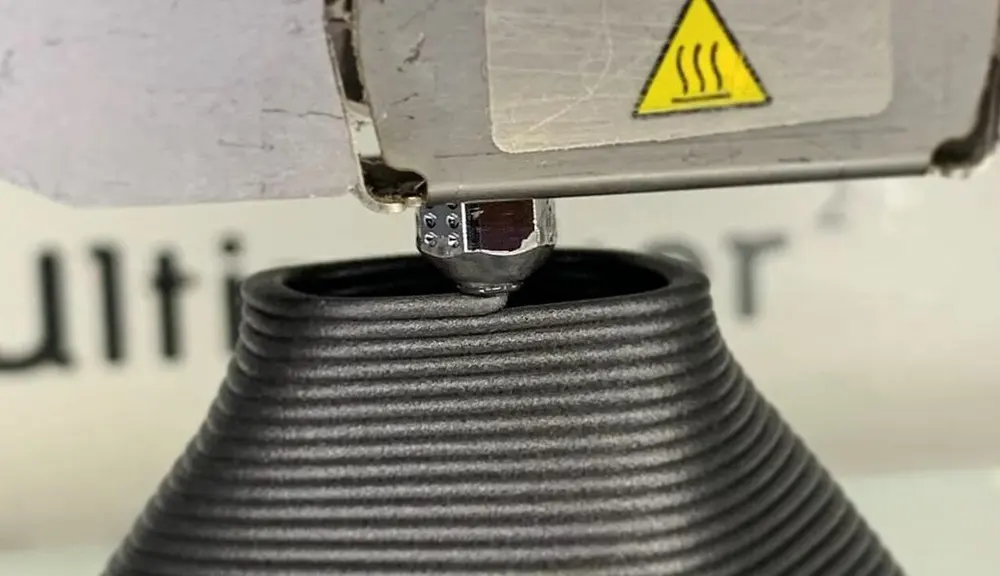
- Vase mode: Vase mode, sometimes known as spiral mode, is a special printing mode that turns a model into a vase using only one wall for the entire exterior. Vase mode also tells your slicer to print the model with smoother and more natural Z-axis moves, eliminating the usual noticeable Z-seam.
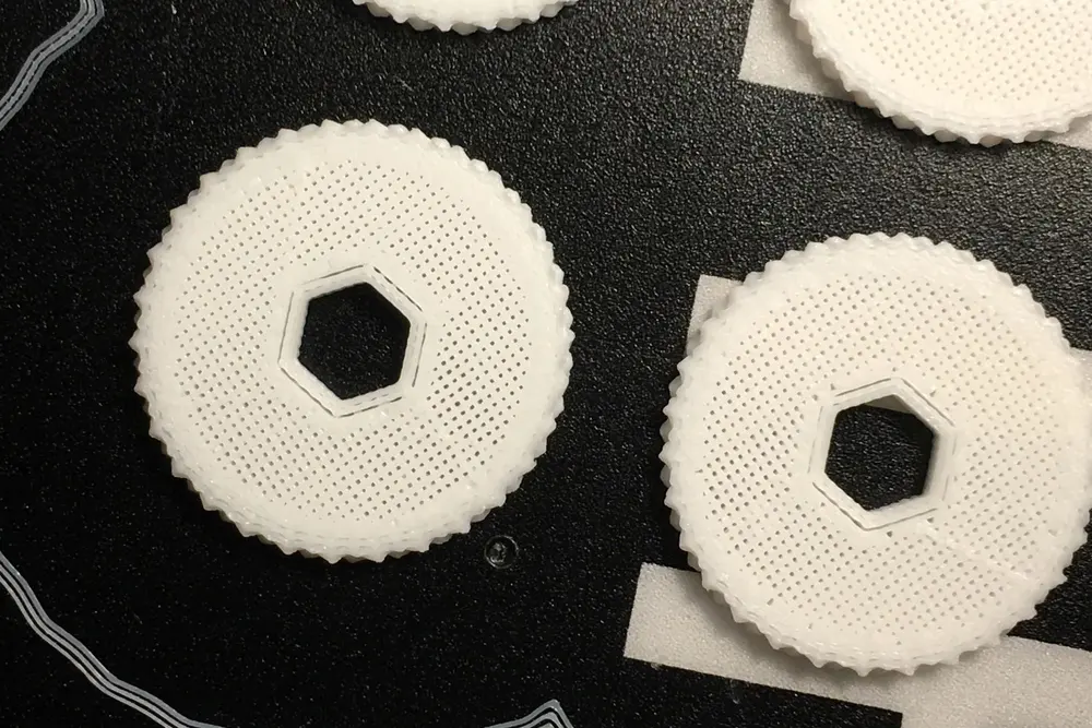
- Fuzzy skin: Lastly, fuzzy skin is a rare but fun 3D slicer setting that’s somewhat relevant to the wall thickness. Turning on fuzzy skin tells your printer to slightly shake the nozzle when it prints the outer wall. This yields a fuzzy texture on the exterior sides and is a cool and unique way to use your slicer if it has the setting (Cura does).