Incorporating threads in your parts can sometimes be the ultimate undoing of your assemblies. There are a lot of design rules and the precision needed to manufacture threads is substantial. Beyond that, these features require a bit of extra thought and care to ensure that they work as designed. Get them right and the assembly could last for years. Done wrong and you’re in for a world of hurt.
External vs. Internal Threading
This is pretty basic, but important. An easy way to remember this difference is that you’ll find external threading on screws and bolts—it’s external to the hardware. Internal threads reside inside the main part. They accept, and lock in, screw and bolt threads. You’ll find more details on external and internal threading later in this design tip.
Thread Pitch
When we talk about threads on bolts and screws, it’s not a one-size-fits-all kind of scenario. In addition to metric threads, there are three primary kinds of imperial measure threads that are part of the Unified Thread Series.
- UNC (coarse pitch): 20 threads per inch (tpi)
- UNF (fine pitch): 28 tpi
- UNEF (extra fine pitch): 32 tpi
Note that adding UNEF thread pitch requires our precision machining service, accessible via our quoting system. For example, if you want to incorporate a #4-40 screw, you know that a #4 screw—which has a thread diameter of 0.11 in. (2.794mm) has 40 threads per inch, meaning extra fine pitch.
The good news is that when you use our system to assign a particular type of screw to a hole, the desired thread pitch comes along for the ride. Less worries are always good, right?
Where Can I Place a Thread?
Really, a thread can be placed almost anywhere that makes sense for the turned or milled part and your assembly’s needs. As long as the area in which the thread will go is accessible to our equipment, you’re good to go, but if there are obstructions, our design analysis software will let you know that threading is impossible in that location, but it’s always a good idea to follow our guidelines to keep you on track.
Even though it seems like there aren’t a lot of placement restrictions when it comes to threading, the depth of an internal thread is important to consider. If the thread depth exceeds the maximum depth for the tooling, we may have to drill through from both sides of the hole in order to complete the process. When that happens, it’s important to know that your threads will not be continuous from one end to the other, but there are options we’ll go over in the next section.
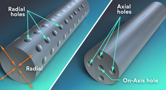
With turned parts, there are three types of holes you can use to accommodate internal threads:
- On-axis: holes that go straight through the center of a turned part, starting at one end
- Axial: holes that start at one end of a part, but don’t go perfectly through the center
- Radial: holes that pierce through the exterior arc of a turned part
Internal Threads
Internal threads are machined using a single-lip threading tool—not a traditional threading tap. On parts with internal-hole features in need of threading, the actual threads need to be removed from your CAD model, leaving only the pilot diameter. Our design analysis software recognizes a hole for threading if:
- it falls within the diameter range for the desired thread and,
- is on one of the three cardinal axes for milling or,
- is perpendicular to the axis of revolution for turning
FacFox supports right-hand threaded holes on machined parts for UNC and UNF threads ranging from a #2 and up to 1/2 in. metric threads are also available, ranging from M2 to M12. Location and method of manufacturing may limit some threads from becoming eligible.
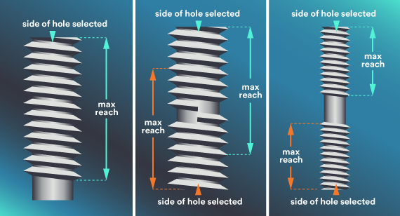
In machining internal threaded holes, a hole may be longer than what our threading tools are able to reach. In this case, you have a few options depending on your needs:
- With a long through hole that exceeds the maximum reach, select the hole from the side that you anticipate the screw to be started from (see image 1 in three-panel illustration above). If your screw is required to pass the entire way through the part, you would also have to pass a tap through the hole (in a secondary process) to complete it.
- You can also select both sides of the feature to be threaded (see image 2 in illustration above) but notice the maximum thread depths as they overlap with each other in the hole. This raises concern with threading the features from both sides, because you risk cross-threading and a screw may not pass all the way through the part cleanly. As long as the threads don’t intersect (see image 3), selecting threads from both sides is typically fine.
One important consideration has to do with the various diameters involved with creating threads. There are three measures you have to think about: the major (wide) thread, minor (narrow) thread, and the diameter of the pilot hole, into which your threaded feature will go.
If your designs instruct your manufacturer to mill out a pilot hole that’s the same diameter as the major (wider) thread, the hardware you use will never fit properly in the hole. It would just drop in, and in a moment that will truly bum you out, the screw is likely to spin around endlessly in the hole. There would be nothing for its thread to grab onto. At that point, your only choice would be to use larger hardware, which might not be functionally acceptable or consistent with your design. Save yourself some trouble: Make sure that any threaded feature’s pilot hole reflects the minor diameter of your thread. Most CAD programs have built-in wizards to help with this process.
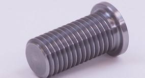
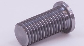
External Threads
The great thing about external threads on turned parts is that the thread can extend the length of the part, as long as your parts qualify for turning. We use a custom threading tool with a selection of thread sizes, depths, and placements within the part geometry. However, our advanced turning process offers external threads on the centerline of the part, and live tooling that allows threading of internal holes, as long as they follow similar guidelines as milling.
We offer external threading for on-axis, axial, and radial holes. Milling external threads is done in two stages. The first set of threads go halfway around your turned part, followed by thread milling on the other side. The two sides meet along the centerline of your part. This process works well for 1/2-inch threads, but we do advise chasing the threads to remove excess material or smooth out mismatches in threading.
Smaller external threads such as a #6-32 are much more difficult to produce with a ball or flat end mill as a larger radius would be left in the root of the thread because the pitch is too tight. You need to chase the threads with a thread-cutting die in order to remove the remaining material. On many parts, a 0.008 in. (0.2032mm) to 0.016 in. (0.4064mm) radius would be left.
Just like internal threads, external thread design requires that the thread be removed from the CAD model in order for our software to recognize it. Additionally, please model your external threads for milling; don’t model them for turning. After you receive your quote for turning, you will have the ability to select the appropriate thread size.

How to Incorporate Threading Into Your Quotes
In our quoting system—adding threaded features is pretty simple. Our software recognizes holes that could potentially include threading and then asks you what kind of threaded hardware you want to use there. As a potential convenient timesaver, you will have the option to give all holes in your CAD the same threading treatment in UNC, UNF, or metric, or you can choose to select each individually. A quick heads-up: Doing a bulk assignment could give you threads where you weren’t expecting them.
Selecting both internal and external threads on part features is easy in our system. On the Thread Assignment tab of your quote, you will notice a fully interactive model that allows you to select which threaded features are available. Each eligible feature is highlighted, and you can manually select threads.
If a thread you want isn’t available, you may need to double-check the diameter of your features to make sure they are within the guidelines for threading. Note that while reviewing our threading charts, you can toggle between milled and turned options within each tab to review the availability of threads for each method of manufacturing. All threads need to be selected and saved before proceeding with an order. If you change your manufacturing process or material at any point, please check the Thread Assignment tab again as selections could change.
Many CAD packages allow you to display threaded features in a few different ways including tap drill, cosmetic thread, or by the major diameter of the thread. We suggest selecting the pilot diameter as long as it is designed at approximately 75% of the thread diameter.
The CAD file should then be submitted in a file format other than .STL; we discourage uploading .STL file formats for machined parts because our software is unable to recognize features like pilot holes in that format. You should use a neutral file format such as .IGES or .STEP, if possible.
On milled parts that require external threads, you must design the threads on your part as this would then be in our standard milling procedure that uses ball and flat end mills. As stated earlier, this wouldn’t be the preferred method for producing threads as you may be required to perform a secondary process of chasing a cutting die over the threads to ensure the parts can be assembled correctly.
On turned parts, external threading improves greatly because the part is spinning on center and a sharp single-lip threading tool can produce a quality thread. The design of an external turned thread is similar to that of the internal hole. Remember that you must remove the threads so our software can digitally view the outside diameter to determine the type of thread needed.
Inserts: Alternatives to Threading
For most metal parts, threading is a great way to achieve a strong bond between elements of your assembly. But sometimes that’s not enough, especially with parts made from weaker materials, such as plastics and aluminum. That’s where inserts come in handy. For example, if you’re working with plastic parts, an important thing to remember is that their threads inevitably will wear out much more quickly than those on metal parts. The solution? Consider incorporating special coil inserts in plastic parts to ensure longer part life. These rugged little disks allow you to get strong threading, even on weaker material. Essentially, you’ll design a hole in the desired location, and you can add the inserts to your parts later. There’s a fair amount of flexibility as coil inserts are available with both UNC and UNF threads ranging from a #2 to 1/2 in., and metric from M2 to M12. We will mill out the hole to your specification and prep it to receive your insert. FacFox is optimized for HeliCoil brand inserts and we recognize standard sizes and lengths.
Tying Threads Together
FacFox offers threaded features for milled parts in plastic and metal, and threaded features on turned parts are only available in metal materials at this time. We can accommodate UNC, UNF, and metric threads along with coil inserts (but do not supply or install the coil inserts). If you have any remaining questions on threading, feel free to contact an applications engineer at info@facfox.com.
| THREADING FOR INJECTION MOLDING |
|---|
| While screw threads were really designed for metal parts, we see examples in molded parts every day.
Designing threads for molded parts requires some changes to your design strategy to ensure that these softer materials can still offer usably strong threads. Our design tip on molded threads covers the subject to help you get past the hurdles. |