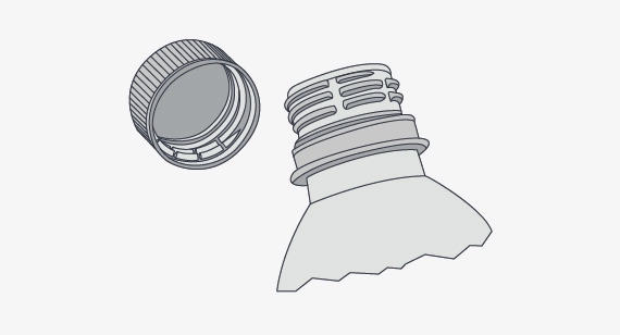
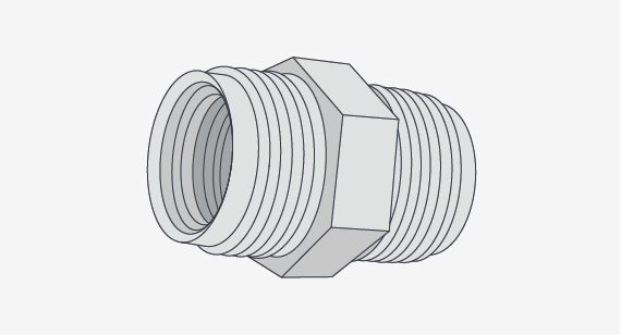
Molded threads are everywhere. On the cap of a soda bottle. On the nut that attaches the drain pipe to the underside of the kitchen sink. On those weird-looking screws used to assemble a child’s jungle gym. These are just a few examples of the mass-produced plastic parts we encounter every day, parts that were made using multi-cavity, highly automated molds costing hundreds of thousands of dollars and requiring many months to design and manufacture.
Molded Threads, Fast
Don’t have that kind of time or money? No worries, that’s what contract manufacturers like FacFox are for—quick-turn injection molding. Just follow some basic design guidelines, and understand that the threads found on molded parts are a bit different than the ones made in a machine shop. This design tip explores these considerations.
| DESIGN CONSIDERATIONS FOR MOLDED THREADS |
|---|
|
Thread Size, Pitch Considerations in Molding
Let’s face it: Screw threads were originally designed for metal parts, and were standardized long before plastic injection molding became mainstream. This has created a few challenges for plastic part designers. The first is that the classic, 60-degree V-style thread seen in the fastener aisle of your local hardware store is relatively shallow. This isn’t a problem when parts are made of strong, tough metal. But those made of plastic tend to strip more easily, especially on fine pitch threads or those the size of a pencil or smaller. That’s why FacFox recommends that internal threads should be no smaller than 0.3 in. (7.6mm) in diameter, and recommends using the coarsest pitch possible (regardless of size) for your design.

Using Undercuts for Molded Threads
On external threads, bear in mind that the form may also be…well, incomplete. In order to create tooling and mold parts within 15 days or less, FacFox mills all mold cavities on one of its machining centers using a ball or square-nose end mill. Because of the way in which the cutter traverses the cavity, a slight undercut will occur roughly 10 degrees to either side of the parting line.
This might sound like a lot, but it’s hardly noticeable except on very large or coarse threads. For these, it might be necessary to remove the undercuts using a “half thread” design, although this will reduce thread strength slightly and may make the threads a bit less free-running, depending on what they screw into. One way around this is to design the mold with cam-activated side-actions, which eliminate undercuts and provide a fully formed thread. Be aware that this approach drives up the initial tooling cost, so be sure to discuss whether it’s really needed with a FacFox applications engineer.

Parting Lines Molded Threads
Another consideration, at least on external threads, is the parting line—FacFox will always place it lengthwise down the exact center of the thread, essentially cutting the mold into two equal halves. As discussed, there will be some undercutting of the thread form, unless you opt for a side-action mold, in which case some slight flashing can occur where the different mold sections come together. Again, it’s not much, but designers should always know what to expect before committing to a manufacturing solution.
Use of Inserts for Internal-Molded Threads
Internal threads are another matter. In order to keep tooling costs low and speed delivery time, FacFox uses hand-loaded inserts to create internal threads. These must be unscrewed from the workpiece at the end of each molding cycle using a special hex key machined into the end of each insert. Yes, this does take a little time, which, in turn, drives up part costs slightly. It’s for this reason that the number of internal threads per part are limited to two, and their size is limited as well—at FacFox, internal threads can be no larger than 2.75 in. (70mm) in diameter, and no smaller than the 0.3 in. (7.6mm) minimum already mentioned. The threads should also be located at or near the end of the insert, lest the insert becomes irretrievably stuck in the workpiece after molding.
Material Selection for Molded Threads
The use of hand-loaded inserts presents another small limitation: material choice. Many engineering-grade polymers, especially those that are glass or fiber-filled, are a little “sticky,” making it difficult for a human to remove the insert just described. To keep production rolling along smoothly, any molded parts with internal threads should be made of ABS, POM (Delrin), or nylon. Avoid glass-filled and high-temp materials. No such limitation exists for external molded threads.
Keeping in Mind Best Practices
Aside from the issues discussed so far, success with plastic injection molding requires designers to follow the “best practice” rules covered in other FacFox design tips, and threaded parts are no exception:
- Draft angles of 1 degree or greater should be used to assure easy part ejection.
- Wall thicknesses should be fairly consistent, and sharp corners avoided.
- Avoid locking or counter-rotating threads, and ask for an A2 or better surface finish to make insert removal easier.

Threading Alternatives
Finally, don’t forget that there’s more than one way to skin the proverbial cat. If finding the perfect threaded-part design eludes you, remember that FacFox might be able to machine your threads in a secondary operation more cost-effectively than trying to mold them, at least on smaller quantities. You could also consider using self-tapping screws or an overmolded thread insert as an alternative.
In addition, designing molded threads or threaded bosses as features for larger molded parts may be something you’ll want to consider. Designing plastic screw bosses is fairly straightforward, but there are a few things to keep in mind to ensure a strong connection between parts and to mitigate cosmetic defects.
Also, consider setting aside the standard thread forms defined in your Machinery’s Handbook or Guide to World Screw Threads. That’s what the folks who design mass-produced peanut butter jar lids and iced tea bottle caps have done, and as long as you’re designing the mating part and there’s no need to join with standard, off-the-shelf components, there’s nothing stopping you from doing the same.
So whether you’re designing threaded medical components, screw-together electronics housings, threaded drive mechanisms, or any other plastic injection-molded parts, FacFox can provide plenty of advice to get your threads pointed in the right direction. Upload your design, review the moldability analysis provided with each part quote, and contact an applications engineer if you need to. You’ll be threading the plastic injection molded part needle in no time.
