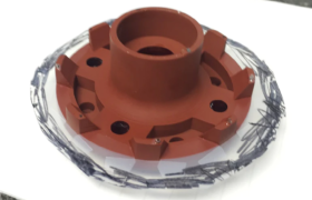
Urethane casting provides end-use, rigid or flexible plastic parts with production-level quality. Built without expensive and time-consuming hard tooling, FacFox’s urethane-casting process uses a 3D printed master pattern and silicone molds to deliver high-quality, short-run parts up to 30 in. long.
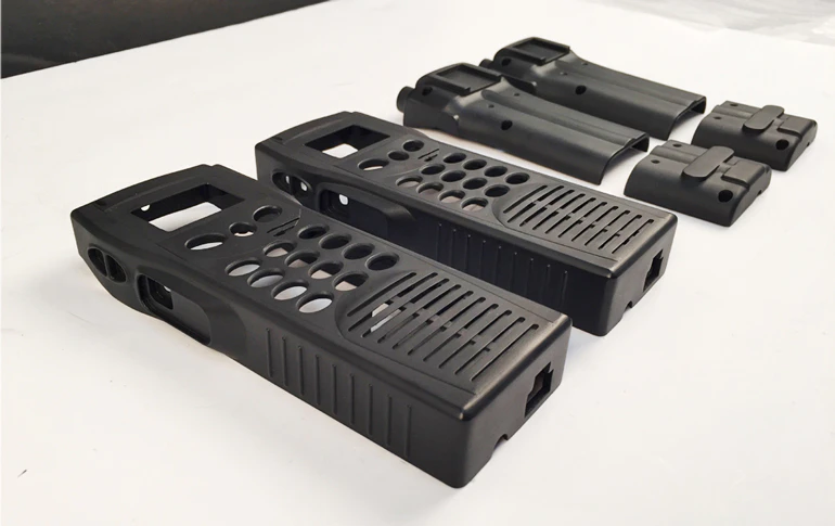
When producing a part with urethane casting, a master should be printed in SLA (stereolithography) or PolyJet 3D (PJ3D). Similar precautions to designing parts for SLA and PJ3D should be taken when designing a part for urethane casting, to ensure that the part resembles its desired properties.
The finished dimensions of urethane-cast parts depends on the accuracy of the master model, part geometry, and casting material. In general, a shrinkage rate of +0.15% is expected.
The Process
Step One
First, a master pattern is printed in either PolyJet 3D (PJ3D) or stereolithography (SLA) to provide an accurate silicone mold. Sometimes tape is placed on flat surfaces to allow for crisp, clean removal of the cast part during post-processing.
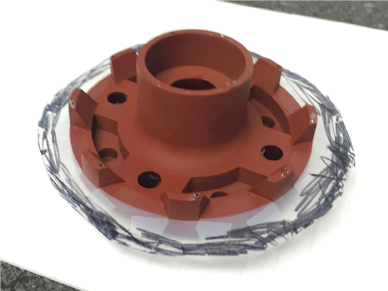
Step Two
Next, the master pattern is encased in liquid silicone to form an accurate mold.
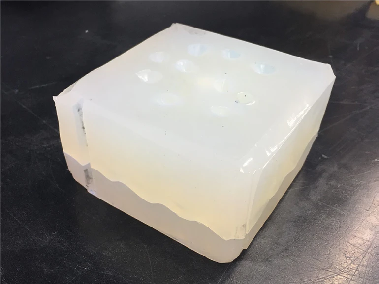
Step Three
After the mold cures, it is cut into distinct halves and the pattern is removed. This cavity is used for casting the end product.
Note: Features that may fatigue, such as through-holes, are replaced with dowels.
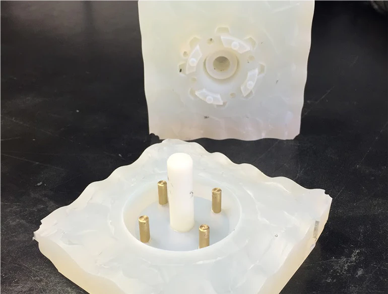
Step Four
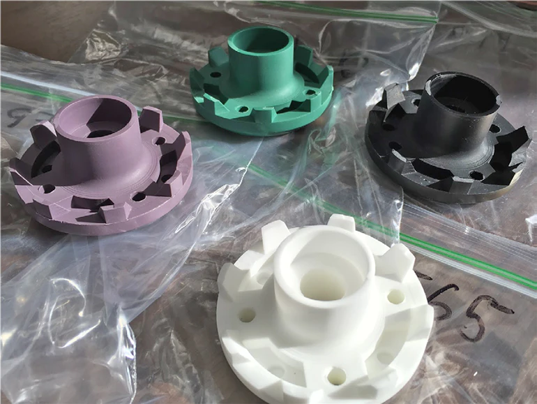
Once the mold tool is created, FacFox’s production team uses urethane and other resins to fill the voids. The material will cure and be removed from the tool. This process repeats until the project is finished.
General Tolerances
- ± 0.010 in. or ±0.003 in. per inch, whichever is larger, is typical. Irregular or overly thick geometries may cause deviances or deflection due to shrinkage.
- A shrinkage rate of +0.15% can be expected due to thermal expansion of the liquid, and the response of the flexible mold.
- Surface finish is externally smoothed to a satin or matte surface. Grow lines may be present on internal or difficult-to-access features. Polishing or custom finishes must be clearly defined and agreed upon at the point of order.
- FacFox can offer urethane-casted parts as large as 30 in. long.
Wall Thickness
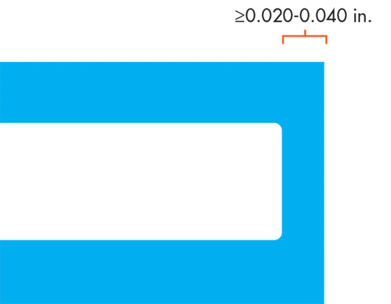
FacFox recommends a minimum wall thickness of 0.040 in. (1 mm). However, there are cases where thinner walls down to 0.020 in. (0.5 mm) are possible on small parts. The larger the part, the larger the wall should be to ensure proper support. Though the casting process makes it possible to vary wall thickness throughout a part, a uniform wall thickness will decrease the risk of deformation due to shrinkage and stress when curing. Design walls should be at least 0.020 in. or 0.040 in. thick, depending on the size of the overall part, to ensure proper support.
Drafts
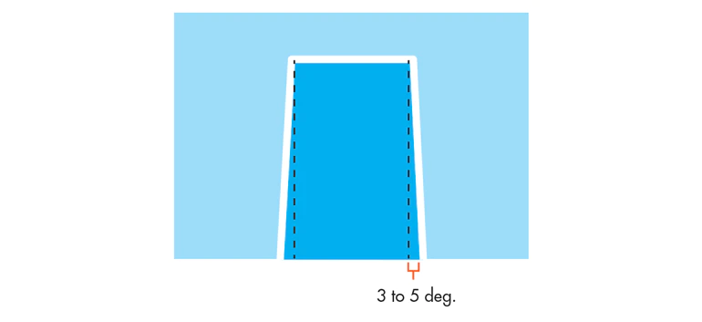
Drafting can also affect production speeds. If a part is easier to remove from the mold, it could generally be done faster. In addition, the amount of time exponentially increases if a few parts get stuck, or have to be damaged to remove them from the mold.
When urethane casting, incorporating drafts is not required, but it can extend the life of the mold. If possible, adding 3-5 degrees of draft will significantly reduce strain on the part when being pulled from the mold. Still, be sure to consider any other production methods that the prototype will be going through and design accordingly.
Joints Between Parts
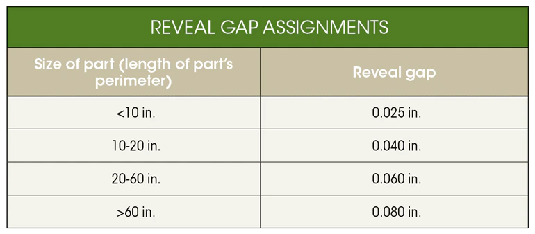
Urethane casting can create parts with joints or overlapping features. FacFox recommends incorporating a reveal gap and the length of the step in a tongue and groove joint based on the size of the part, due to tolerances and paint thickness.
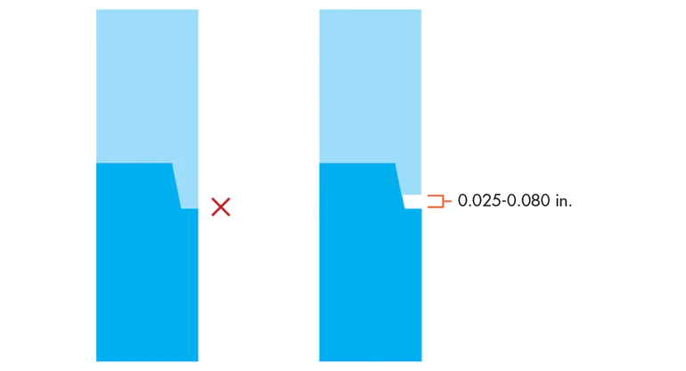
Include a reveal gap in any tongue and groove joints based on the part’s perimeter.
The table presents some of the guidelines for assigning a reveal gap based on the size of the part (part’s perimeter).
Letters and Logos
Urethane casting produces an excellent quality of raised and recessed letters and logos because of the accuracy inherent with the silicone mold. FacFox recommends leaving at least 0.050-in. space between letters. The width should be twice the measurement of the height. The larger the radius of the letters, the more accurately they will read.
Features
Ribs
Adding ribs to a design is an excellent way to improve the strength and rigidity of molded parts. Adding this type of reinforcement will decrease the part’s ability to bend (increasing the bending stiffness) without having to make the part thicker.
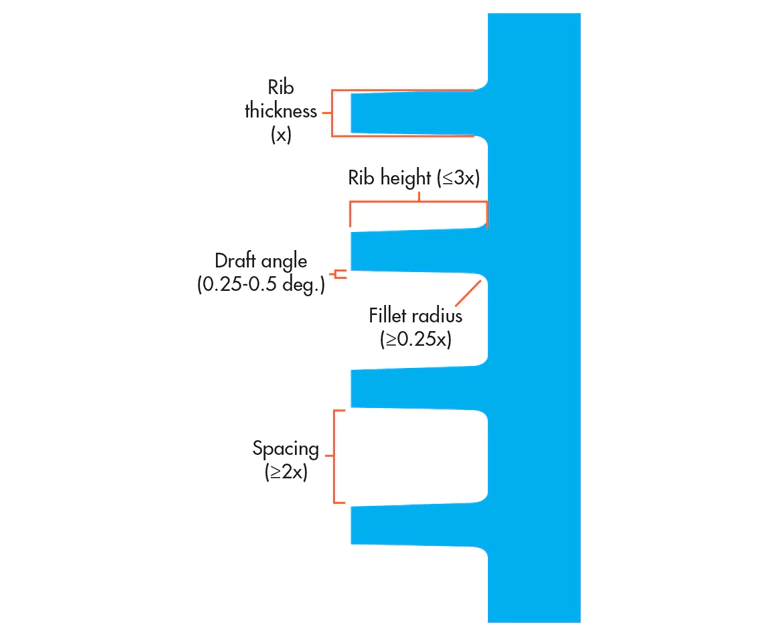
Rather than designing one very tall rib, multiple ribs will be more effective in increasing the part’s bending stiffness.
Guidelines for Ribs
- Height: Generally, the length of the rib determines the rib strength, so a longer rib will provide greater reinforcement. Unfortunately, when casting in urethane, a long rib can be difficult to mold. As a result, FacFox recommends that the rib does not exceed a height of three times its thickness to ensure that the part does not deviate from the design.
- Width: The width of a rib at the intersection with the part should range from 40% to 60% of the thickness of the part, with a fillet radius of at least 25% of the part’s thickness to ensure the maximum rib strength.
- Draft angle: It is important to draft a rib to reduce the possibility of sinking. FacFox recommends making the draft angles of each side between 0.25 and 0.5 deg. The draft angle of each side should be equal. Note: For a textured surface, add an additional 1.0-deg. draft for every 0.025-mm (0.001 in.) depth of texture.
- Spacing: FacFox recommends spacing consecutive ribs at least two times the thickness away from each other to maximize the impact of each rib.
- Orientation: Ribs should be oriented in a way that maximizes the bending stiffness of the part. This depends on how and where the load or stress will be placed on the part. If the ribs are oriented in the wrong direction, they will have little to no effect on the stiffness.
Intersections and Sinking
At the point where a rib and part intersects, the part may be susceptible to dipping due to a heavy rib weighing down the surface. Here are some of the ways to reduce the risk of sinking at a rib intersection:
- Fillets: FacFox recommends making the radii of fillets at least one quarter of the thickness of the part. Fillets reduce the stress on the surface and can reduce sink on the opposite side of the part.
- Coring (lightweighting) the part will reduce material as well as help maintain a uniform wall thickness throughout the part.
- Rib thickness: At a rib intersection, the width of the rib should only be 40% to 60% of the thickness of the part. Thinning down the walls will avoid excess sinking on the opposite side by decreasing the weight of the rib.
Note: Ribs should only be used when extra reinforcement or support is needed. Often, ribs are placed poorly and do not improve the strength and rigidity of the part. Improper use of ribs could waste material, increase the price, increase the weight of the part, and create molding problems. Please consult our engineering team at info@facfox.com to see if a rib is appropriate for your part.
Bosses
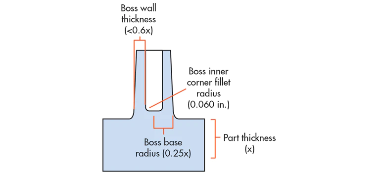
Creating a connecting rib between the boss and the wall, as well as implementing gussets around the boss, can strengthen and further reinforce the boss. FacFox recommends limiting the depth of the boss to only the clearance required when creating a part with a mold to prevent deviation from the intended design.
Bosses are an excellent feature to secure mating parts with screws or fasteners. The base radius of the boss should be 25% of the thickness of the part to prevent the screw or pin from burning when placed into the boss. To reduce the wall thickness and avoid sinking, inner corners of bosses can use a 0.060-in. radius for the fillet. FacFox recommends making the wall thickness for bosses less than 60% of the thickness of the part to ensure minimal shrinkage.
Radii and Fillets
FacFox recommends a fillet with a radius of 0.125 in. on all inside corners, or surface transitions, to increase the strength of the part.
Note: Adding fillets to inside corners significantly improves production quality, and gets you closer to an end-use part.
Inserts
Through-holes: For simple through-holes, dowel rods are placed into the silicone mold to define the feature. Maintaining a line of sight is required when designing for urethane casting to ensure that a dowel rod can be inserted in the mold.
Threads: Threaded inserts can be added to a urethane casting mold in a variety of sizes. To learn more about the features that can be inserted in a urethane casting mold, please contact our engineers at info@facfox.com.
Note: Blind holes and overhangs can be created with an SLA master. However, they do not translate well to urethane casting because they will be inaccessible features. Zero draft features, while possible, pose a slight risk of part breakage/warpage when extracting from the mold.
Materials and Finishing
Urethane casting is conducive to many different types of polyurethane plastics, ranging from rigid to flexible. Some of the most common materials used in the process include:
- Rigid, high-impact urethane
- Rigid, heat-resistant urethane
- Flexible, clear urethane
Coloring options for urethane casting include:
- Cast-in colors
- Painted after casting
Standard casting will result in a relatively smooth surface with excellent rigidity (high flexural modulus).
There are certain advantages and drawbacks to each coloring option:
Cast-in colors
Pros
- No chipping
- No peeling
- Specific texture
Cons
- Surface finish depends on master pattern finish
- Color may not be exact to specifications
Paint
Pros
- Variety of colors
- Gloss level
- Uniform surface appearance
- Eliminates visible lines left from parting object from mold
- Great UV stability
Cons
- Prone to scratches in post-processing
- Additional labor after casting; typically results in higher cost
