Design for injection molding
There are several factors that may affect the quality of the final product and the repeatability of the process. To yield the full benefits of the process, the designer must follow certain design guidelines.
In this section, we outline common defects of injection molding and basic and advanced guidelines to follow when designing parts, including recommendations for keeping the costs to a minimum.
Common injection molding defects
Most defects in injection molding are related to either the flow of the melted material or its non-uniform cooling rate during solidification.
Here is a list of defects to keep in mind while designing a part for injection molding. In the next section, we’ll see how you can avoid each of them by following good design practices.
Warping
When certain sections cool (and as a result shrink) faster than others, then the part can permanently bend due to internal stresses.
Parts with non-constant wall thickness are most prone to warping.
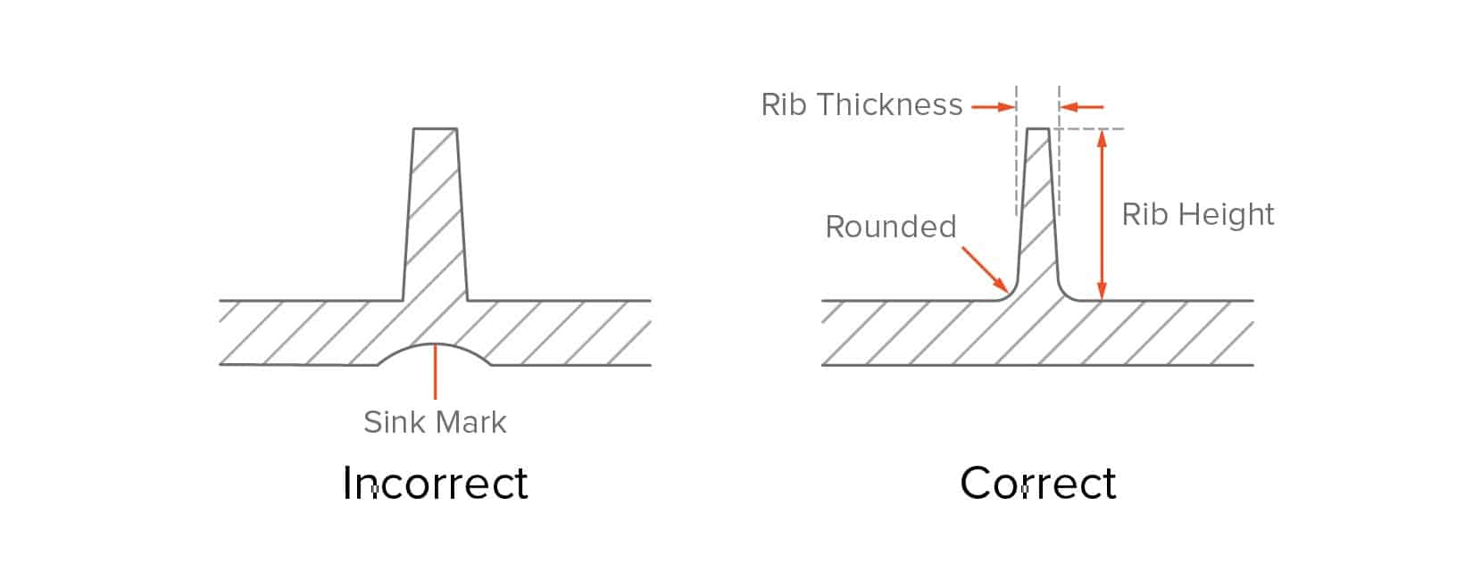
Sink marks
When the interior of a part solidifies before its surface, a small recess in an otherwise flat surface may appear, called a sink mark.
Parts with thick walls or poorly designed ribs are most prone to sinking.
Drag marks
As the plastic shrinks, it applies pressure on the mold. During ejection, the walls of the part will slide and scrape against the mold, which can result to drag marks.
Parts with vertical walls (and no draft angle) are most prone to drag marks.
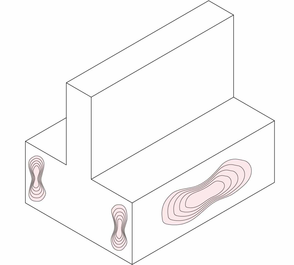
Knit lines
When 2 flows meet, small hair-like discolorations may develop. These knit lines affect parts aesthetics, but also they generally decrease the strength of the part.
Parts with abrupt geometry changes or holes are more prone to knit lines.
Short shots
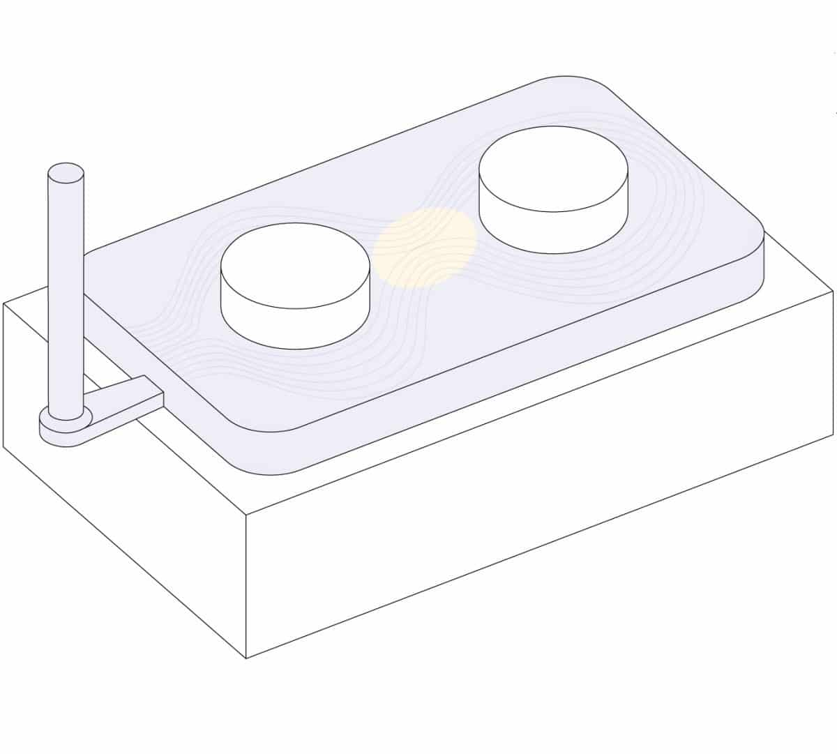
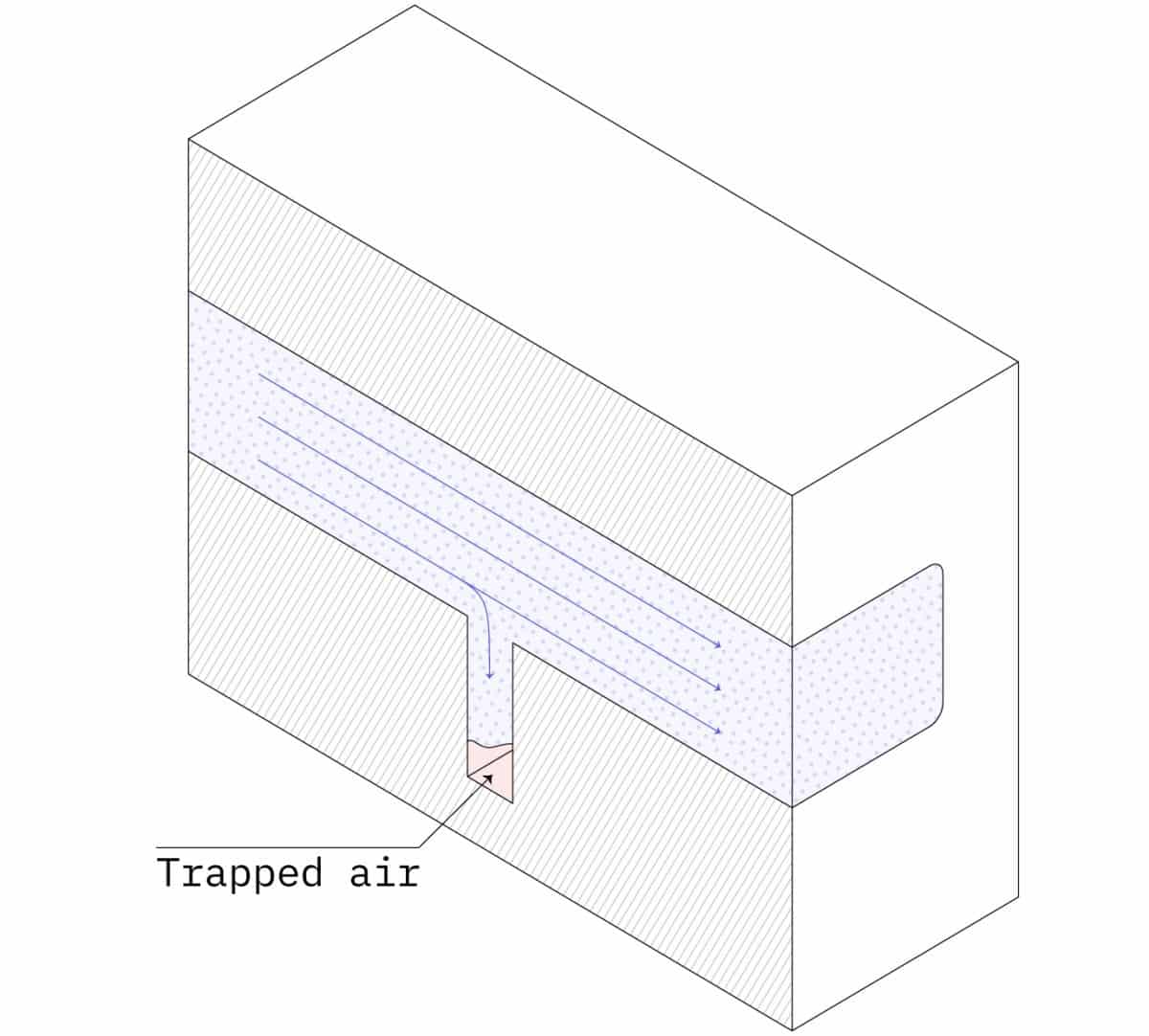
Trapped air in the mold can inhibit the flow of the material during injection, resulting in an incomplete part. Good design can improve the flowability of the melted plastic.
Parts with very thin walls or poorly designed ribs are more prone to short shots.
Design rules for injection molding
One of the biggest benefits of injection molding is how easily complex geometries can be formed, allowing a single part to serve multiple functions.
Once the mold is manufactured, these complex parts can be reproduced at a very low cost. But changes to the mold design at later stages of development can be very expensive, so achieving the best results for the first time is essential. Follow the guidelines below to avoid the most common defects in injection molding.
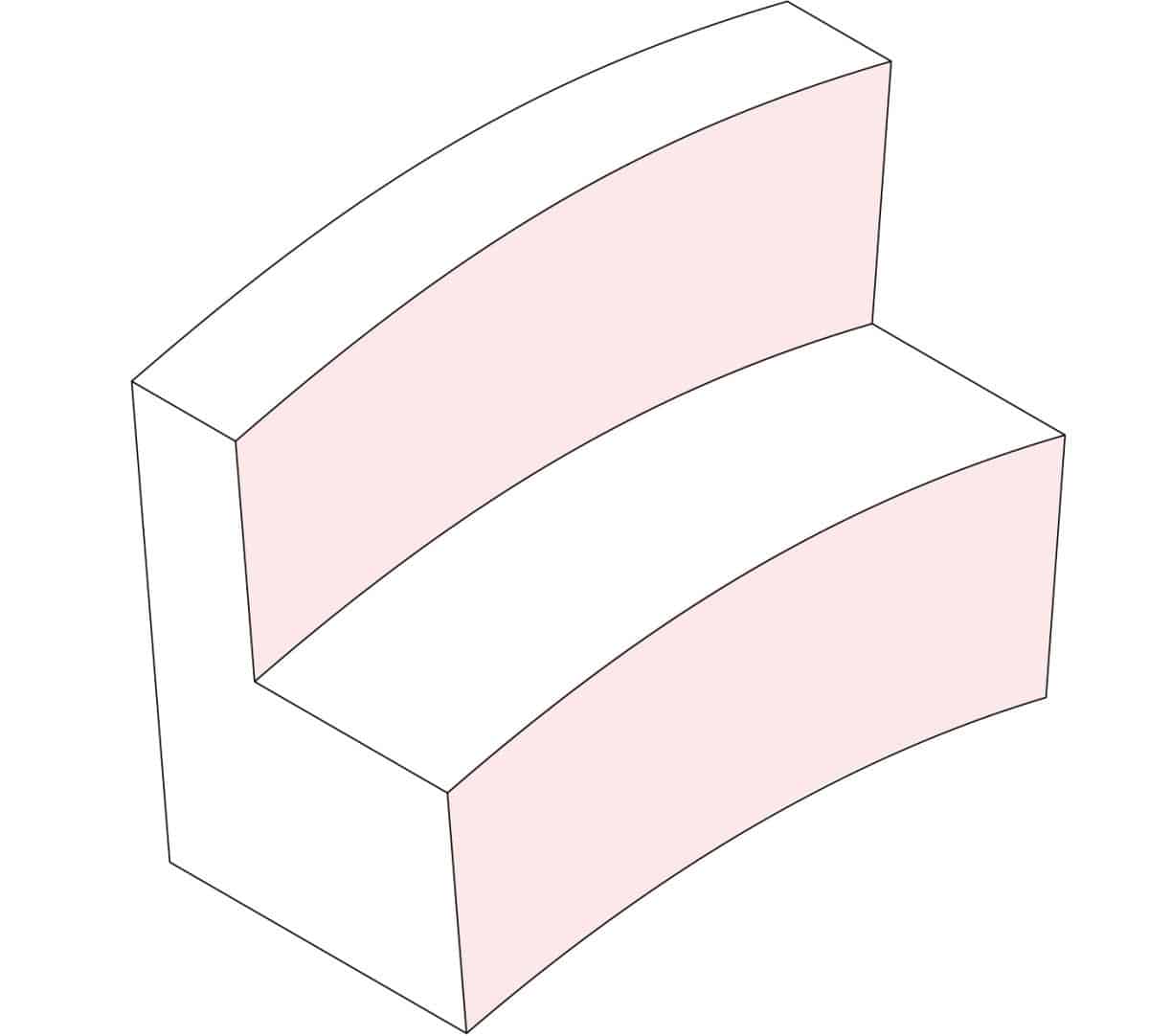
Use a constant wall thickness
Use a uniform wall thickness throughout the part (if possible) and avoid thick sections. This is essential as non-uniform walls can lead to warping or the part as the melted material cools down.
If sections of different thickness are required, make the transition as smooth as possible using a chamfer or fillet. This way the material will flow more evenly inside the cavity, ensuring that the whole mold will be fully filled.
Wall thickness between 1.2 mm and 3 mm is a safe value for most materials. The next table summarises specific recommended wall thicknesses for some of the most common injection molding materials:
| Material | Recommended wall thickness [mm] | Recommended wall thickness [inches] |
|---|---|---|
| Polypropylene (PP) | 0.8 – 3.8 mm | 0.03” – 0.15” |
| ABS | 1.2 – 3.5 mm | 0.045” – 0.14” |
| Polyethylene (PE) | 0.8 – 3.0 mm | 0.03” – 0.12” |
| Polystyrene (PS) | 1.0 – 4.0 mm | 0.04” – 0.155” |
| Polyurethane (PUR) | 2.0 – 20.0 mm | 0.08” – 0.785” |
| Nylon (PA 6) | 0.8 – 3.0 mm | 0.03” – 0.12” |
| Polycarbonate (PC) | 1.0 – 4.0 mm | 0.04” – 0.16” |
| PC/ABS | 1.2 – 3.5 mm | 0.045” – 0.14” |
| POM (Delrin) | 0.8 – 3.0 mm | 0.03” – 0.12” |
| PEEK | 1.0 – 3.0 mm | 0.04” – 0.12” |
| Silicone | 1.0 – 10.0 mm | 0.04” – 0.40” |
For best results:
- Use a uniform wall thickness within the recommended values
- When different thickness are required, smoothen the transition using a chamfer or fillet with length that is 3x the difference in thickness
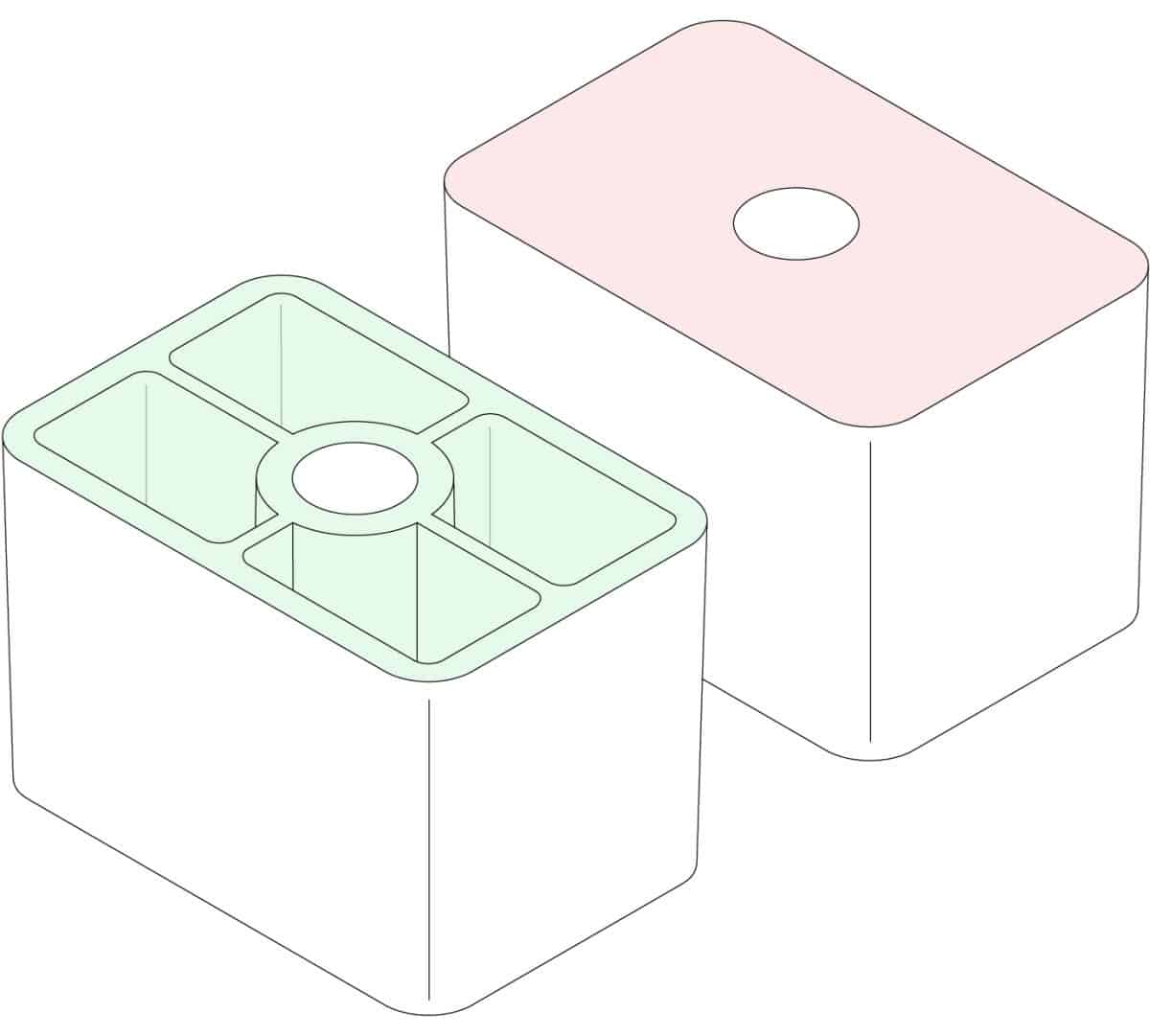
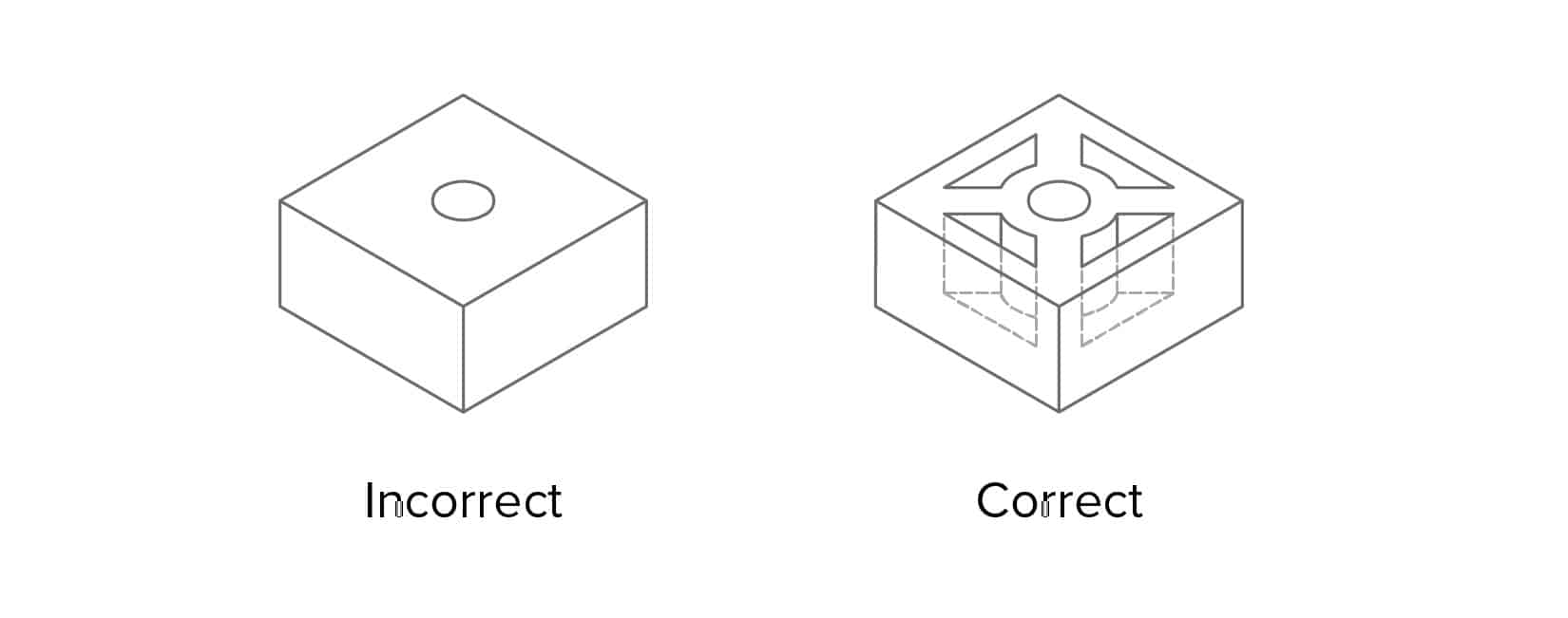
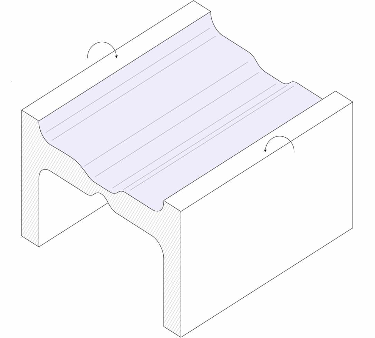
Hollow out thick sections
Thick sections can lead to various defects, including warping and sinking. Limiting the maximum thickness of any section of your design to the recommended values by making them hollow is essential.
To improve the strength of the hollow section, use ribs to design structures of equal strength and stiffness but reduced wall thickness. A well-designed part with hollow sections is shown below:
Ribs can also be used to improve the stiffness of horizontal sections without increasing their thickness. Remember though that the wall thickness limitations still apply. Exceeding the recommended rib thickness (see below) can result in sink marks.
For best results:
- Hollow out thick sections and use ribs to improve the strength and stiffness of the part
- Design ribs with max. thickness equal to 0.5x the wall thickness
- Design ribs with max. height equal to 3x the wall thickness
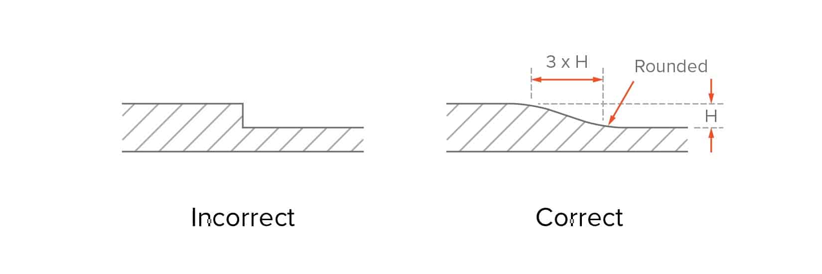
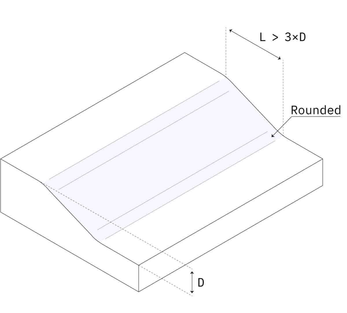
Add smooth transitions
Recommended: 3 × wall thickness difference
Sometimes sections with different wall thicknesses cannot be avoided. In these cases, use a chamfer or fillet to make the transition as smooth as possible.
Similarly, the base of vertical features (like ribs, bosses, snap-fits) must also always be rounded.
Round all edges
The uniform wall thickness limitation also applies to edges and corners: the transition must be as smooth as possible to ensure good material flow.
For interior edges, use a radius of at least 0.5 x the wall thickness. For exterior edges, add a radius equal to the interior radius plus the wall thickness. This way you ensure that the thickness of the walls is constant everywhere (even at the corners).
Adding to this, sharp corners result in stress concentrations which can result in weaker parts.
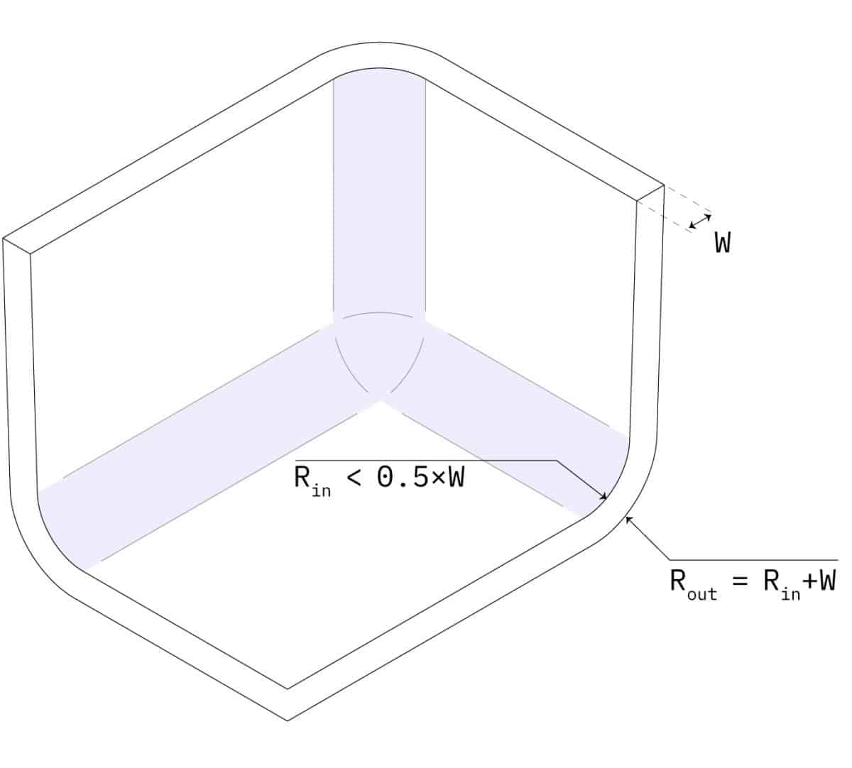
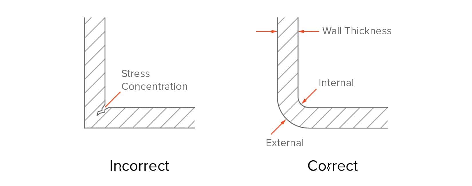
- Add a fillet equal to 0.5x the wall thickness to internal corners
- Add a fillet equal to 1.5x the wall thickness to external corners
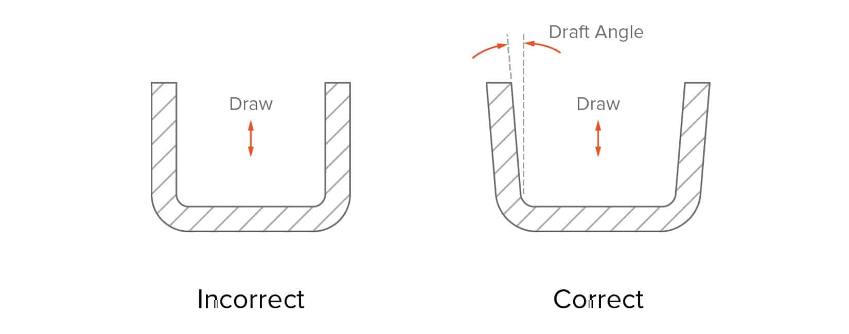
Add draft angles
To make the ejection of the part from the mold easier, a draft angle must be added to all vertical walls. Walls without a draft angle will have drag marks on their surface, due to the high friction with the mold during ejection.
A minimum draft angle of 2° is recommended. Larger draft angles (up to 5o °) should be used on taller features.
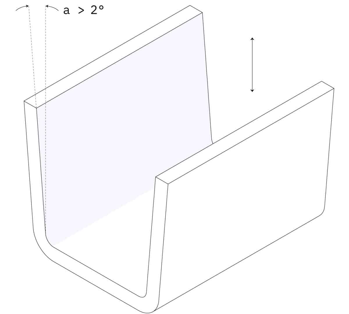
A good rule of thumb is to increase the draft angle by one degree for every 25 mm. For example, add a draft angle of 3o degrees to a feature that is 75 mm tall. Larger draft angle should be used if the part has a textured surface finish. As a rule of thumb, add 1o to 2o extra degrees to the results of the above calculations.
Remember that draft angles are also necessary for ribs. Be aware though that adding an angle will reduce the thickness of the top of the rib, so make sure that your design complies with the recommended minimum wall thickness.
- Add a minimum draft angle of 2o degrees to all vertical walls
- For features taller than 50 mm, increase the draft angle by one degree every 25 mm
- For parts with textured surface finish, increase the the draft angle by 1-2o extra degrees
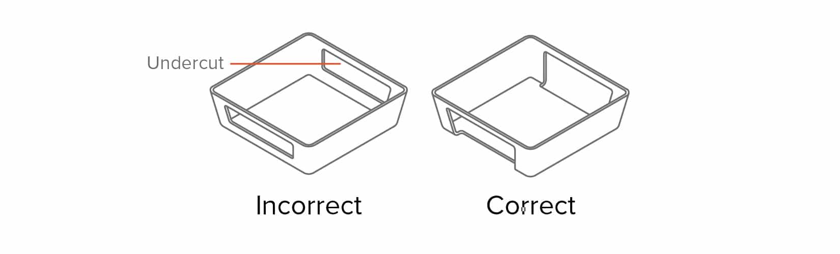
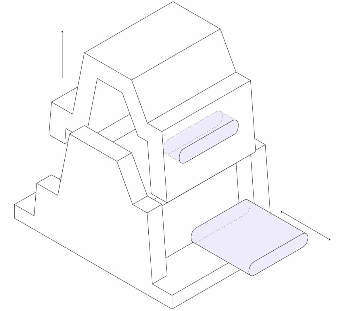
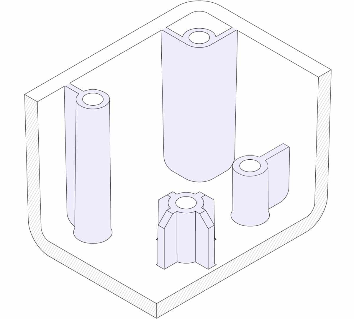
Dealing with undercuts
The simplest mold (the straight-pull mold) consist of 2 halves. Features with undercuts (such as the teeth of a thread or the hook of a snap-fit joint) may not be manufacturable with a straight-pull mold though. This is either because the mold cannot be CNC machined or because the material is in the way of ejecting the part.
Undercuts in injection molding are part features that cannot be manufactured with a simple two-part mold, because material is in the way while the mold opens or during ejection.
The teeth of a thread or the hook of a snap-fit joint are examples of undercuts.
Here some ideas to help you deal with undercuts:
Avoid undercuts using shutoffs
Avoiding undercuts altogether might be the best option. Undercuts always add cost, complexity, and maintenance requirements to the mold. A clever redesign can often eliminate undercuts.
Shut-offs are a useful trick to deal with undercuts on internal regions of the part (for snap-fits) or on the sides of the part (for holes or handles).
Below are some examples of how injection molded parts can be redesigned to avoid undercuts: essentially, the material is removed in the area under the undercut, eliminating the issue altogether.

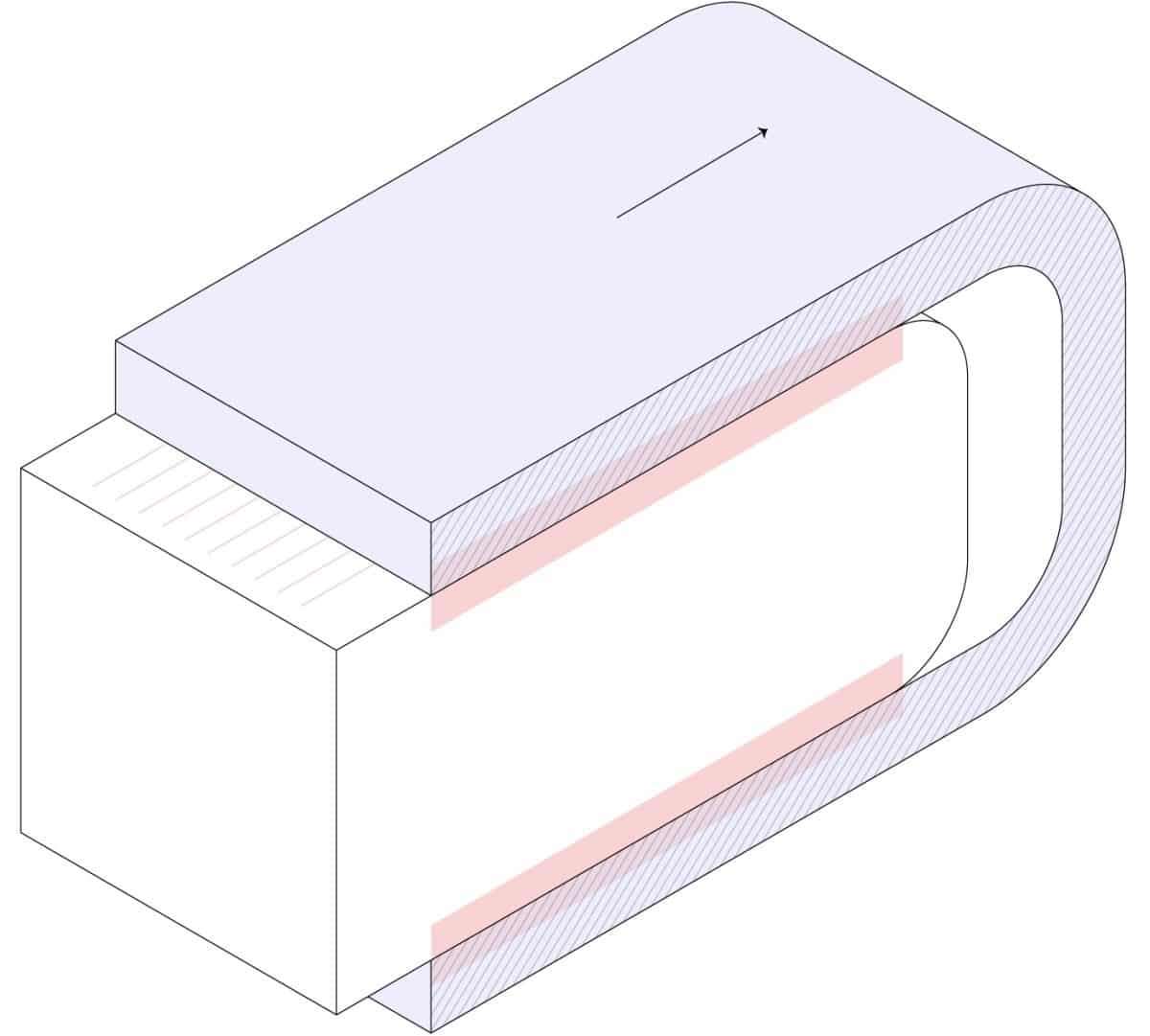
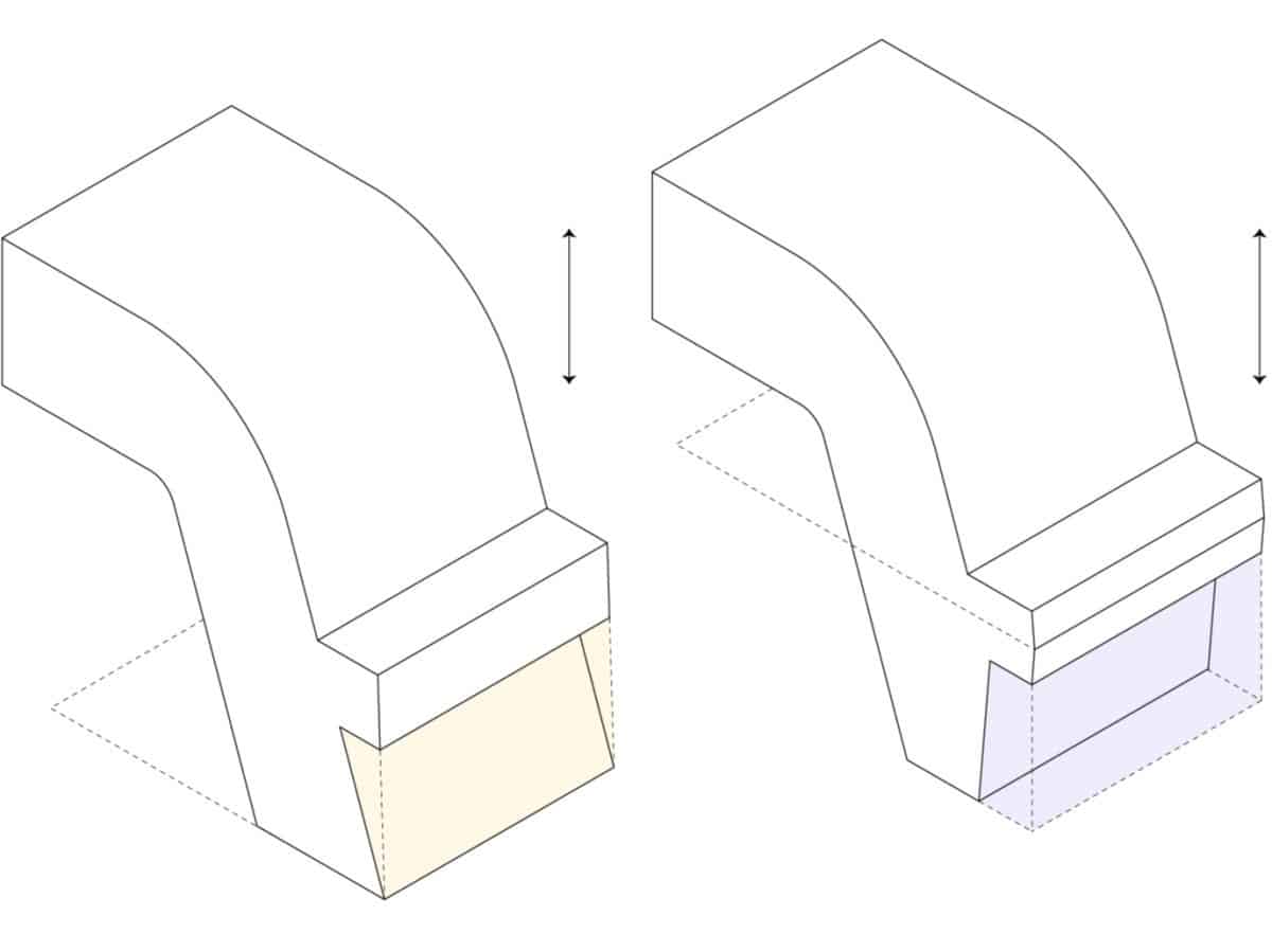
Move the parting line
The simplest way to deal with an undercut is to move the parting line of the mold to intersect with it.
This solution is suitable for many designs with undercuts on an external surface. Don’t forget to adjust the draft angles accordingly.
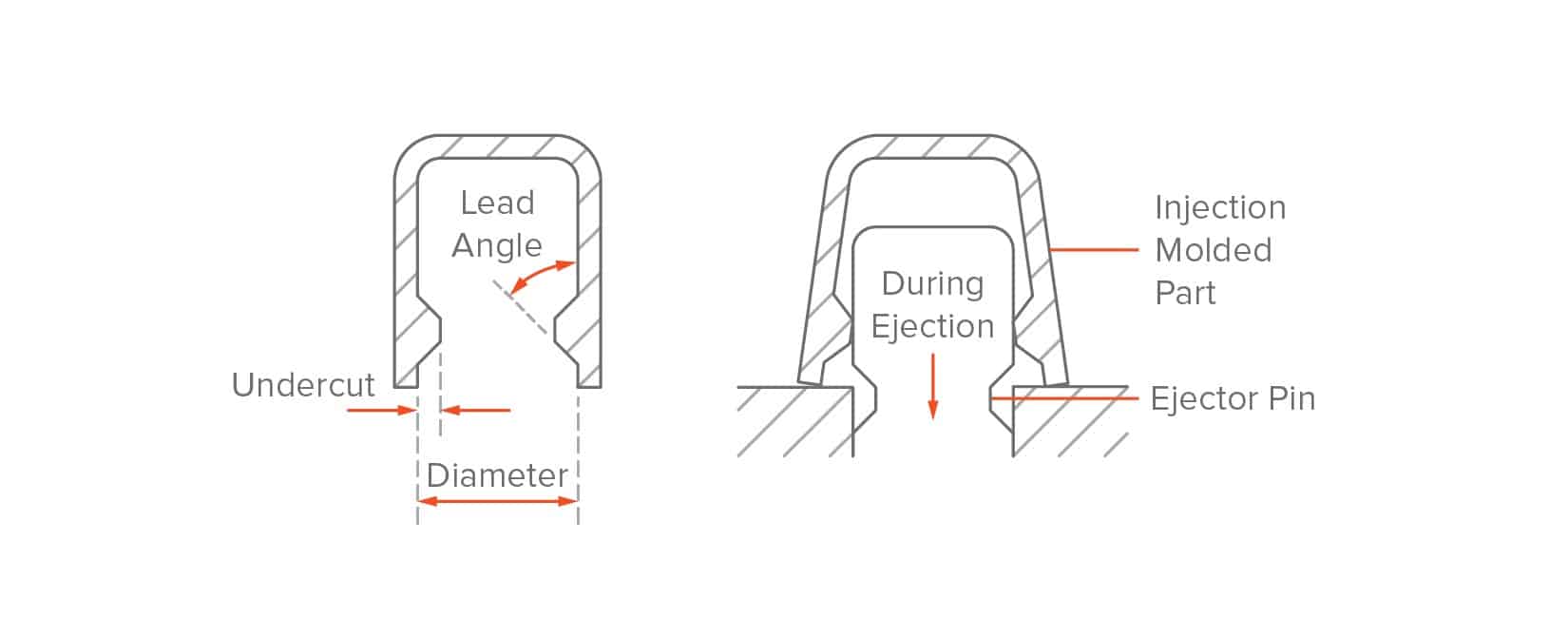
Use a stripping undercut (bumpoffs)
Stripping undercuts (also known as bumpoffs) can be used when the feature is flexible enough to deform over the mold during ejection. Stripping undercuts are used to manufacture the threads in bottlecaps.
Undercuts can only be used under the following conditions:
- The stripping undercut must be located away from stiffening features, such as corners and ribs.
- The undercut must have a lead angle of 30o to 45o degrees.
- The injection molded part must have space and must be flexible enough to expand and deform.
It is recommended to avoid stripping undercuts in parts made from fiber-reinforced plastics. Typically, flexible plastics such as PP, HDPE or Nylon (PA) can tolerate undercuts of up to 5% of their diameter.
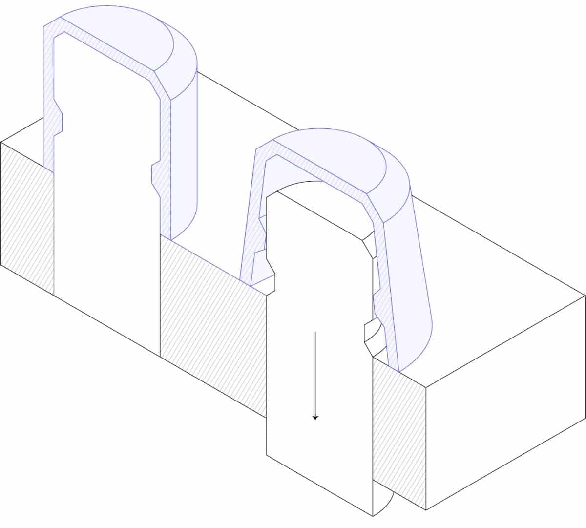
Sliding side-actions and cores
Sliding side-actions and cores are used when it is not possible to redesign the injection molded part to avoid undercuts.
Side-action cores are inserts that slide in as the mold closes and slide out before it opens. Keep in mind that these mechanisms add cost and complexity to the mold.
Follow these guidelines when designing a side action:
- There needs to be space for the core to move in and out. This means that the feature must be on the other side of the part.
- The side-actions must move perpendicularly. Moving at an angle other than 90° is more complicated, increasing cost and lead times.
- Don’t forget to add draft angles to your design as usual, taking in consideration the movement of the side action core.
Common design features
Learn how to design the most common features encountered in injection molded parts with these practical guidelines. Use them to improve the functionality of your designs, while still complying with the basic design rules.
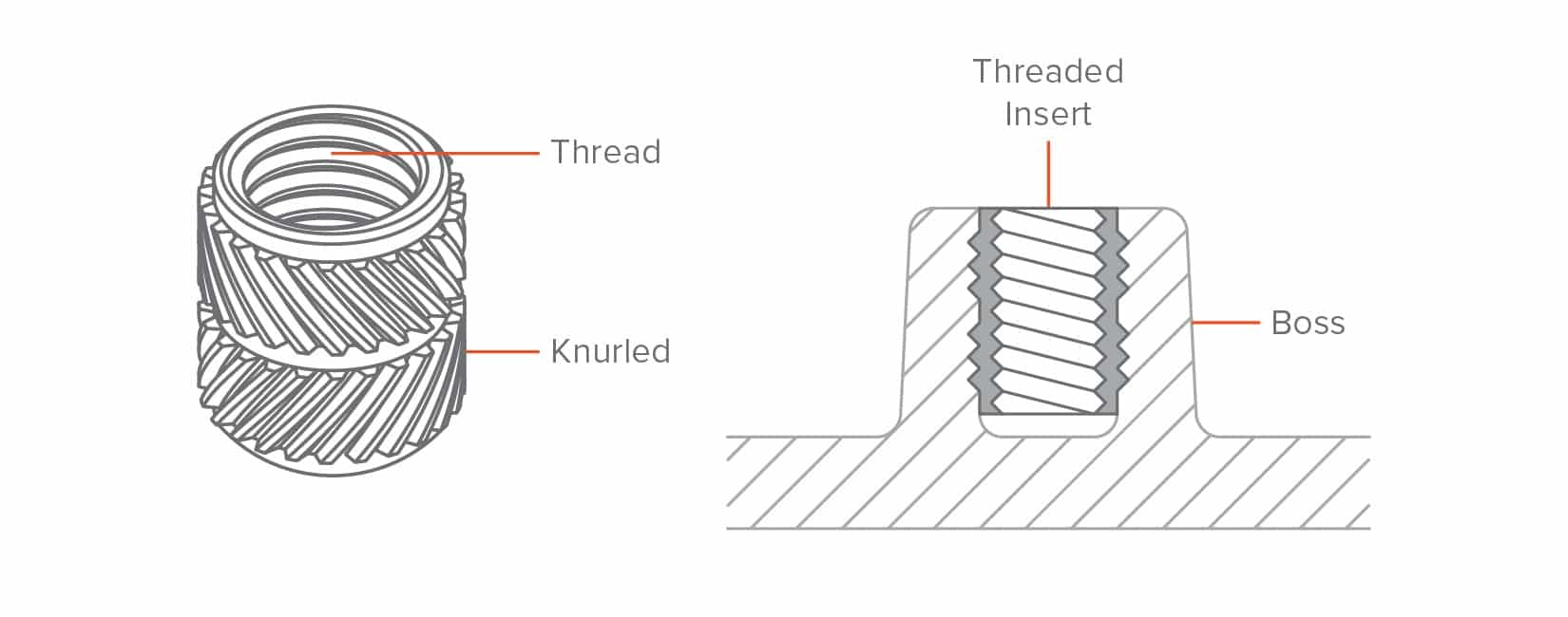
Threaded fasteners (bosses and inserts)
There are 3 ways to add fasteners to an injection molded part: by designing a thread directly on the part, by adding a boss where the screw can be attached, or by including a threaded insert.
Modeling a thread directly on the part is possible, but not recommended, as the teeth of the thread are essentially undercut, increasing drastically the complexity and cost of the mold (we will more about undercuts in a later section). An example of an injection molded part with a thread are bottle caps.
Bosses
Bosses are very common in Injection Molded parts and are used as points for attachment or assembly. They consist of cylindrical projections with holes designed to receive screws, threaded inserts, or other types of fastening and assembly hardware. A good way to think of a boss is as a rib that closes on itself in a circle.
Bosses are used as points of attachment or fastening (in conjunction with self-tapping screws or threaded inserts).
When bosses are used as points of fastening, the outer diameter of the boss should be 2x the nominal diameter of the screw or insert and its inner diameter equal to the diameter of the core of the screw. The hole of the boss should extend to the base-wall level, even if the full depth is not needed for assembly, to maintain a uniform wall thickness throughout the feature. Add a chamfer for easy insertion of the screw or insert.
For best results:
- Avoid designing bosses that merge into main walls
- Support bosses with ribs or connect them to a main wall
- For bosses with inserts, use an outer diameter equal to 2× the insert’s nominal size
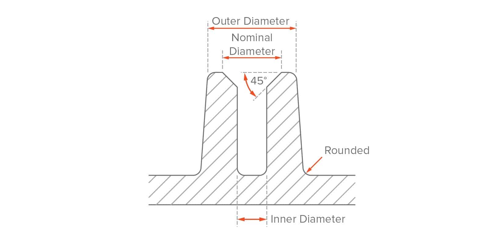
Threads
Metal threaded inserts can be added to plastic Injection Molded parts to provide a durable threaded hole for fasteners such as machine screws. The advantage of using inserts is that they allow many cycles of assembly and disassembly.
Inserts are installed in Injection Molded parts through thermal, ultrasonic or in-mold insertion. To design a boss that will receive a threaded insert, use similar guidelines as above, using the diameter of the insert as the guiding dimension.
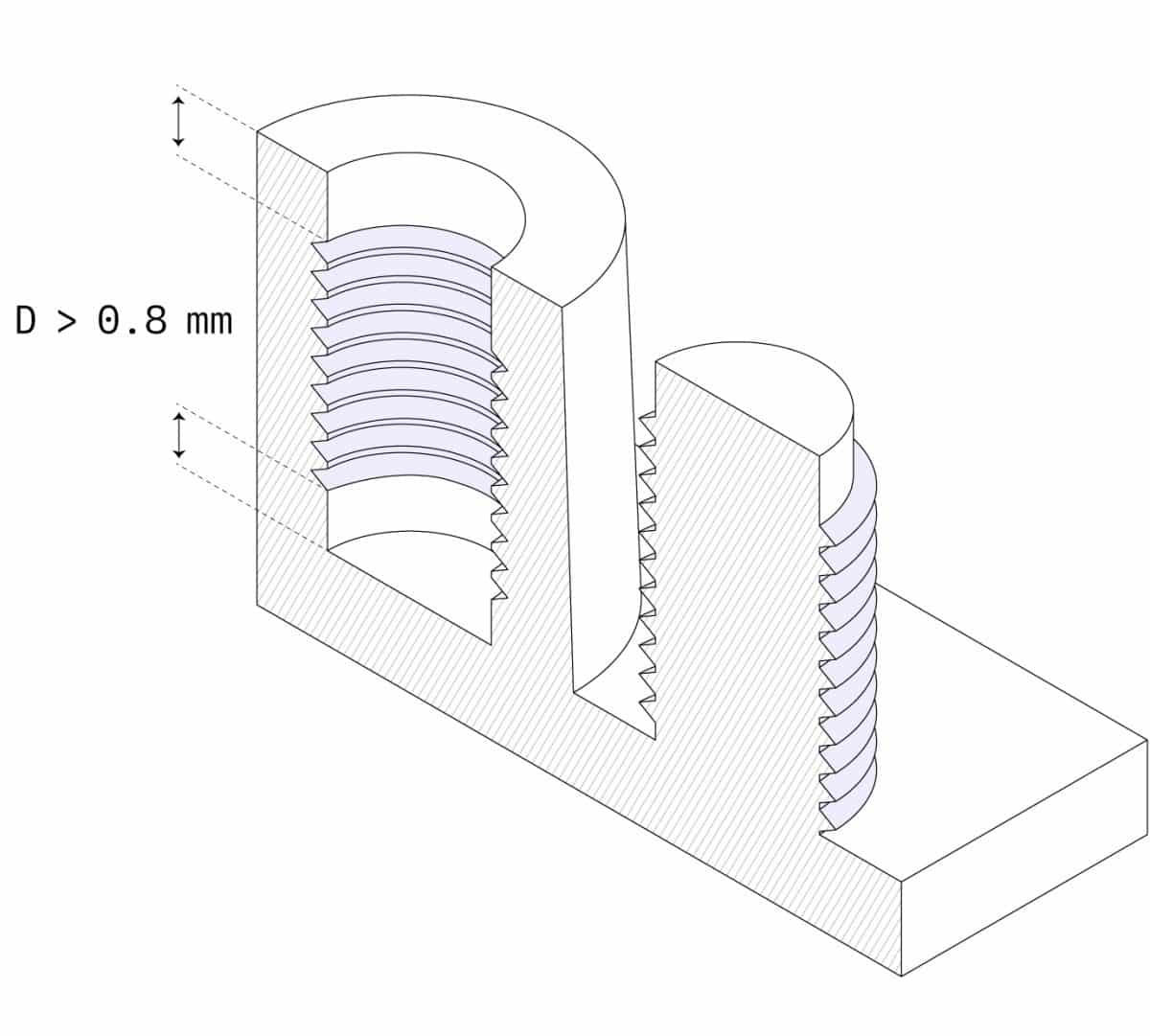
- Avoid adding threads directly on your injection molded part
- Design bosses with an outer diameter equal 2x the nominal diameter of the screw or insert
- Add a 0.8 mm relief at the edges of the thread
- Use a thread with a pitch greater than 0.8 mm (32 threads per inch)
- Use a trapezoidal or buttress thread
Best way to deal with the created undercuts:
- Use a thread with a pitch greater than 0.8 mm (32 threads per inch)
- For external threads, place them along the parting line
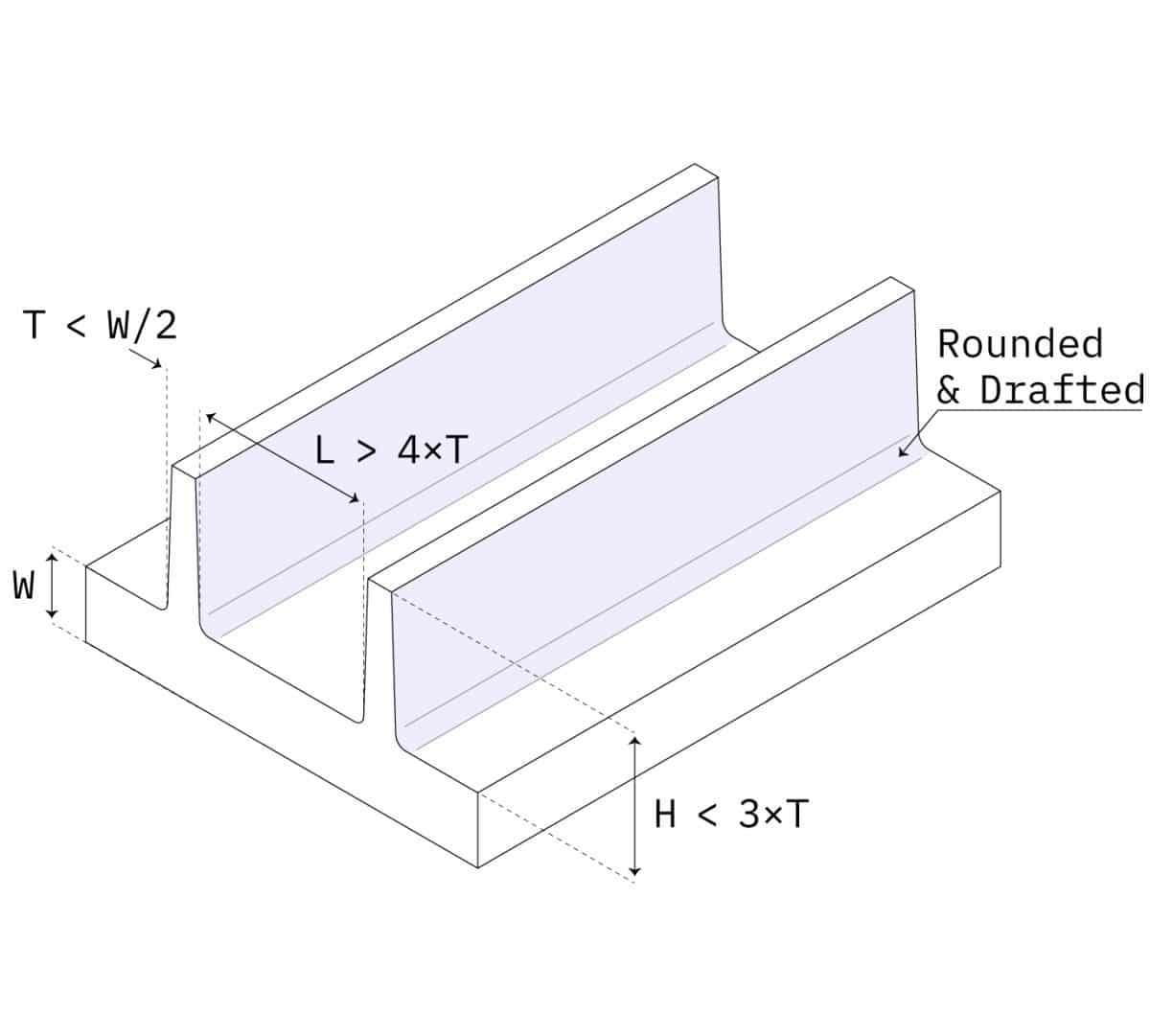
Ribs
When even the maximum recommended wall thickness is not enough to meet the functional requirements of a part, ribs can be used to improve its stiffness.
When designing ribs:
● Use a thickness equal to 0.5 × main wall thickness
● Define a height smaller than 3 × rib thickness
● Use a base fillet with radius greater then ¼ × rib thickness
● Add a draft angle of at least 0.25° – 0.5°
● Add a min. distance between ribs and walls of 4 × rib thickness
Snap-fit joints
Snap-fit joints are a very simple, economical, and rapid way of joining two parts without fasteners or tools. A wide range of design possibilities exists for snap-fit joints.
As a rule of thumb, the deflection of a snap-fit joint mainly depends on its length and the permissible force that can be applied on it on its width (since its thickness is more or less defined by the wall thickness of the part). Also, snap-fit joints are another example of undercuts.
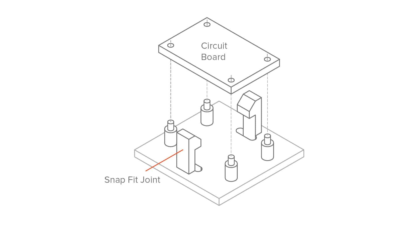
For best results:
- Add a draft angle to the vertical walls of your snap-fit joints
- Design snap-fits with thickness greater than 0.5x the wall thickness
- Adjust their width and length to control their deflection and permissible force
Living hinges
Living hinges are thin sections of plastic that connect 2 segments of a part and allow it to flex and bend. Typically these hinges are incorporated in mass-produced containers, such as plastic bottles. A well-designed living hinge can last for up to a million cycles without failure.
The material used to injection mold a living hinge must be flexible. Polypropylene (PP) and Polyethylene (PE) are good choices for consumer application and Nylon (PA) for engineering uses.
A well-designed hinge is shown below. The recommended minimum thickness of the hinge ranges between 0.20 and 0.35 mm, with higher thicknesses resulting in more durable, but stiffer, parts.
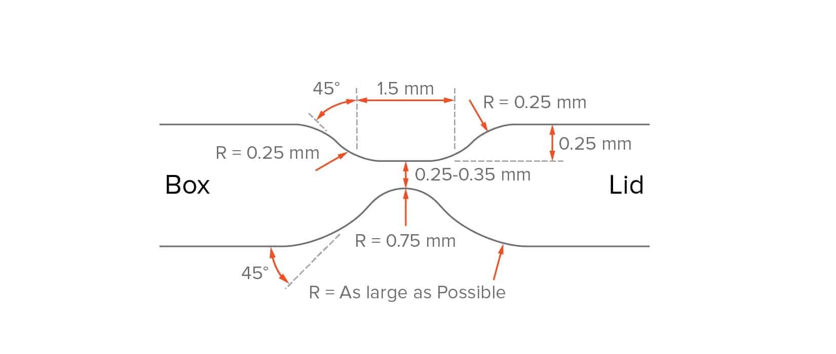
For best results:
- Design hinges with a thickness between 0.20 and 0.35 mm
- Select a flexible material (PP, PE or PA) for parts with living hinges
- Use shoulders with a thickness equal the thickness of the main wall
- Add fillets as large as possible
Crush ribs
Crush Ribs are small protruding features that deform to create friction when different components are pushed together, securing their position.
Crush ribs can be an economical alternative for manufacturing high tolerance holes for tight fits. They are commonly used to house bearings or shafts and other press-fit applications.
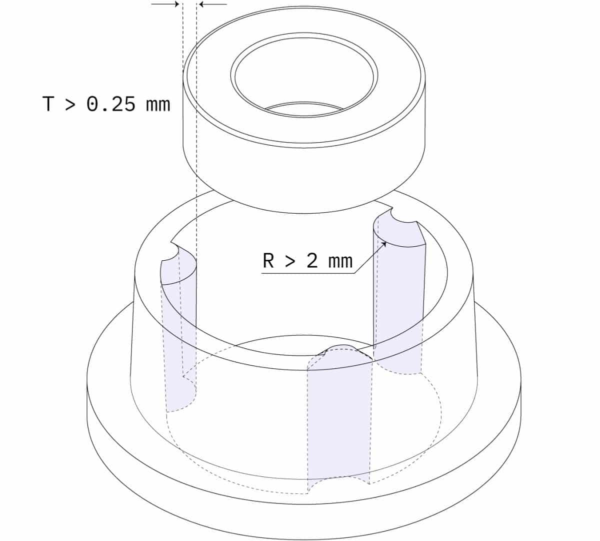
An example of a part with crush ribs is shown below. Using three crush ribs is recommended to ensure good alignment. The recommended height/radius for each rib is 2 mm. Add a minimum interference of 0.25 mm between the crush rib and the fitted part. Because of the small surface contact with the mold, crush ribs can be designed without a draft angle.
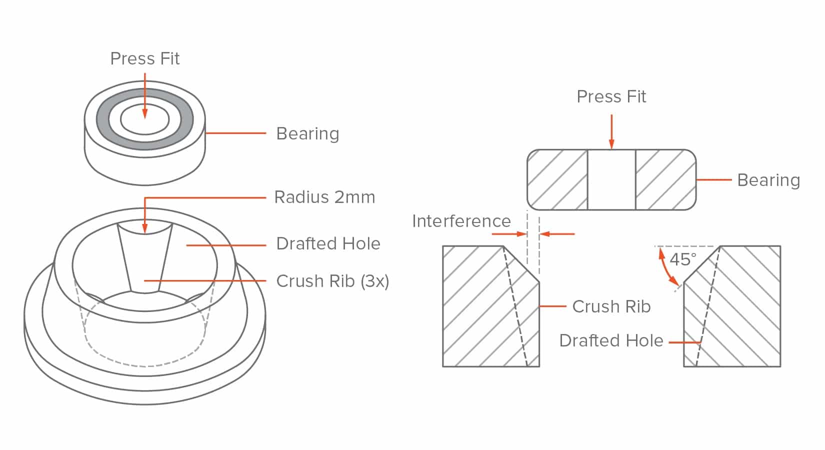
- Add a minimum interference of 0.25 mm between crush rib and the component
- Do not add a draft angle on the vertical walls of a crush rib
Lettering and symbols
Text is a very common feature that can be useful for logos, labels, warnings, diagrams, and instructions, saving the expense of stick-on or painted labels.
When adding text, choose embossed text over the engraved text, as it’s easier to CNC machine on the mold and thus more economical.
Also raising the text 0.5 mm above the part surface will ensure that the letters are easy to read. We recommend selecting a bold, rounded font style with uniform line thickness, with a size of 20 points or larger. Some font examples include: Century Gothic Bold, Arial, and Verdana.
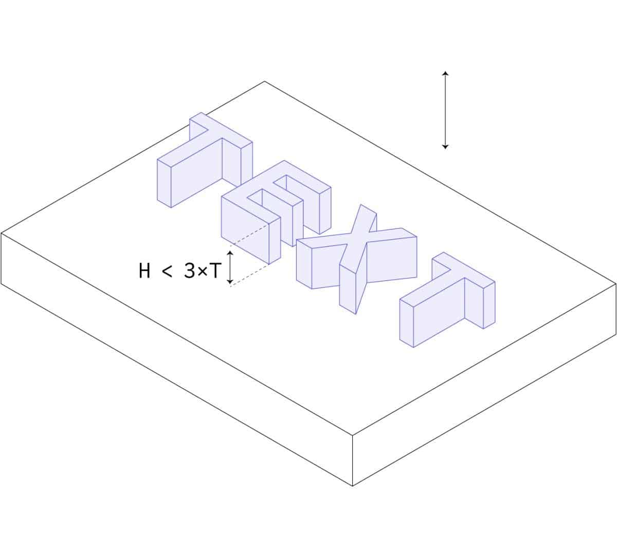
For best results:
- Use embossed text (0.5 mm height) instead of engraved texted
- Use a font with uniform thickness and a minimum font size of 20 points
- Align the text perpendicular to the parting line
- Use a height (or depth) greater than 0.5 mm
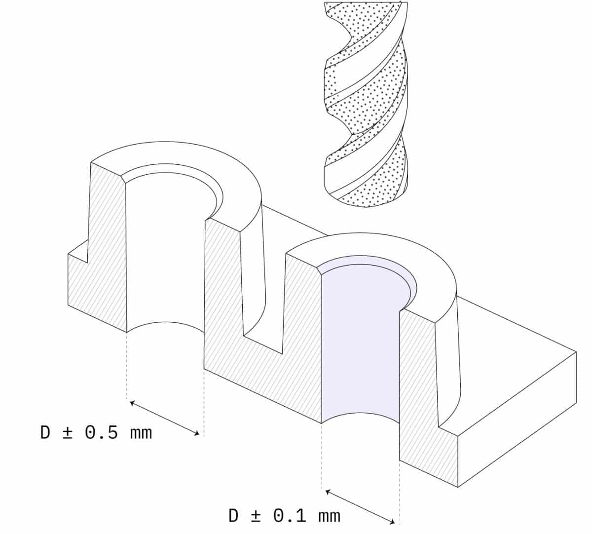
Tolerances
- Injection molding typically produces parts with tolerances of ± 0.500 mm (0.020’’).
- Tighter tolerances are feasible in certain circumstances (down to ± 0.125 mm – and even ± 0.025 mm), but they increase the cost drastically.
- For small production runs (< 10,000 units), consider using a secondary operation (such as drilling) to improve accuracy. This ensures the correct interference of the part with other components or inserts (for example, when using press fits).