3D printing presents tremendous benefits to the conventional architectural workflow. It is possible to print complex designs without the need for skilled manual fabricators, and rapidly iterate on these designs with relative ease. Stereolithography (SLA) 3D printing offers incredibly high surface quality and fine detail, which makes it very suitable for architectural applications. This article covers modeling strategies and software workflows that allow architects and designers to easily integrate 3D printing into their existing design methodology.
Architectural models are conventionally assembled with a variety of materials and components. 3D printers help fuse these components into as few individual parts as possible, but some assembly is still required for two reasons:
1. The constraints of the build volume.
Printers with large build volumes are either cost-prohibitive or compromise on surface quality.
2. The need to show interior detail or materiality.
Certain models require components that come apart to reveal more information about the design.
DESIGNING FOR ASSEMBLY
All 3D models require some preparation before they can be sent to the 3D printer. In the case of architectural models for our industrial SLA 3D printers, this sometimes involves splitting the model into smaller parts to accommodate the size of the building envelope. Parts can then be easily joined together through chemical adhesion or mechanical assembly; the high accuracy of the prints ensures that the parts join together seamlessly.
Strategy Overview
There are several strategies for 3D printing models for assembly. Your strategy will depend on what you hope to represent with the design, and the scale and geometry of the model. Consider these parameters:
- Need to show interior vs. exterior detail
- Ease of split (you’ll want to split it along the least complex part of the model)
- Need to show a certain part of the program: unit typology, structure, floor layout
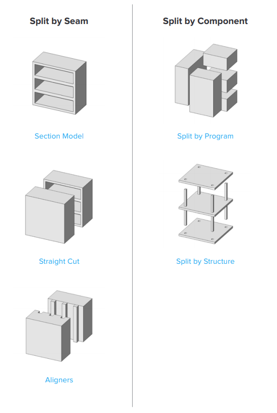
Split by Seam
STRAIGHT CUT
The simplest method for splitting a model is with a straight cut. It is an easy command to perform in most CAD packages. A model of a bridge is split into four parts along its length using straight cuts, one section of which is shown above. Each support underneath is inserted into a mating hole that does not require adhesive. Regardless of which method you choose, if you have a large number of parts (more than 10) it’s helpful to add a unique identifier to each part to help you solve the puzzle during assembly.
Pros:
- Least CAD intensive
- More forgiving for prints that warp or have a higher degree of dimensional variation
Cons:
- Assembly requires manually aligning each part and clamping in place until the adhesive fully bonds them
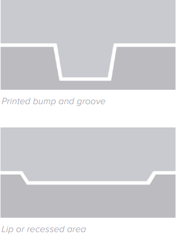
ALIGNERS
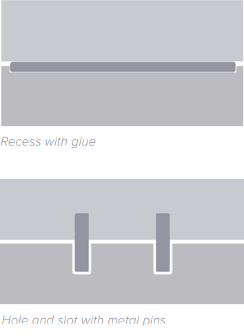
Another approach is to add features to your design that will allow the prints to align themselves. When adding aligners, try to split the model in an area that has the least complex geometry. Use the CAD tool of your preference to split your model and add basic aligners like slots, pins, grooves, recesses, and lips or more complex aligners like dovetails and cuts that follow existing creases in the model. Additionally, it is important to design in a tolerance of ~0.25 mm between mating parts, in order to prevent extra sanding in the post-print stage.
Pros:
- Easy alignment
- Easy to assemble (mating parts help to create more surface area for adhesion)
- High accuracy SLA allows for snug fits with high tolerance, and can be used without glue.
Cons:
- Parts that are not dimensionally accurate will not fit well together. Tall, thin prints are often less dimensionally accurate.
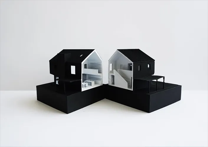
SECTION MODEL
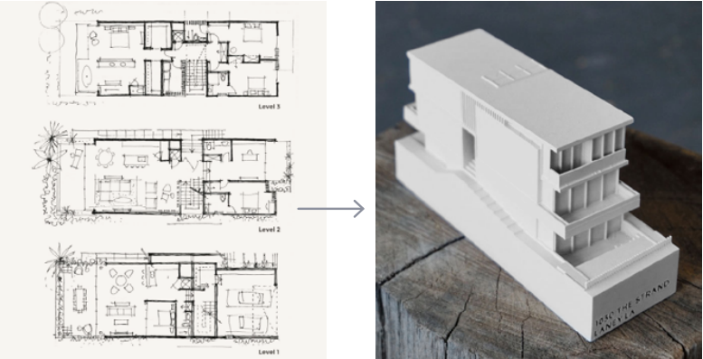
Splitting a model with a seam has the added benefit of showing a section model for designs with compelling interior details. The model can initially be presented as a whole to the client, and then disassembled to reveal interior detail when desired. These examples by LaneyLA show how the same model conveys different types of information based on the open and closed configurations.
Split by Component
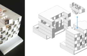
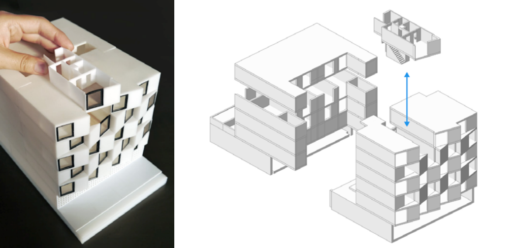
SPLIT BY PROGRAM
By breaking a building down by program, you can present a building as a kit of parts, providing a clear understanding of all the design components without plan and section drawings. You can either print each floor slab separately and then assemble with mating features, or simply print one component of the entire building separate from the rest. A good example is this model from Stanley Saitowitz | Natoma Architects Inc. (SSNAI), who created a model of an apartment complex.
SPLIT BY STRUCTURE
Some models lend themselves to being split up by their structural components, rather than printing as a single block or splitting along a seam. This technique usually works for models that aren’t
characterized by rectilinear forms, such as regular building envelopes, but are instead complex structures, such as detailed components of a building, bridges, pavilions, or airports.
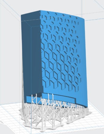
First, break down these models into components that lend themselves to 3D printing with minimal supports. This saves time on post-processing (support removal for delicate models can be tedious) and also saves material cost and print time.
This example of a bridge demonstrates multiple splitting techniques. First, the model is split into multiple parts (figure a). Although these fit on the building platform, they require tedious support removal around the more delicate areas such as cables and railings.
To solve this, each part is broken down into three sub-components: the base plate and railings, vertical tensile cables, and the solar wings on the top (figure b). These can be printed with significantly fewer supports, allowing for easier finishing.
Upon finishing, the components simply need to be assembled with the help of mating features that were included in the design step. Smaller parts are also easier to pack into a single build platform, with the entire bridge being printed in five prints of roughly 100 mL each.
Software Workflow
A good print relies on a well-designed 3D model. This section will go over best practices and workflows for modeling for printability in some of the most common CAD environments: Revit, SketchUp, and Rhino.
Common Workflows
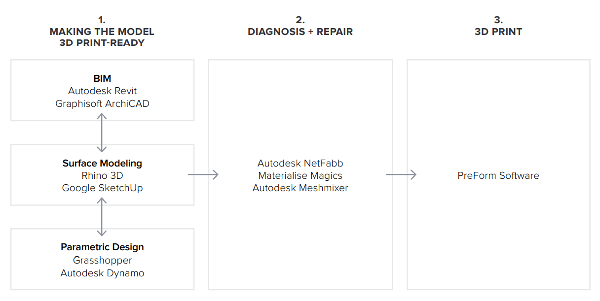
BIM Workflow
Revit → Rhino/SketchUp → Model Diagnosis → PreForm
Though BIM (Building Information Modeling) software is popular amongst architecture firms, it doesn’t always lend itself to directly 3D printable models.
These are some high-level steps that can be taken to produce a 3D printable model from these software. This workflow applies broadly to Autodesk Revit or Graphisoft ArchiCAD software, both of which are parametric BIM modelers.
PREPARE THE FILE
- STEP 1: Create a separate standalone file.
- STEP 2: Manage components: remove ductwork, double glazed windows, HVAC units, and interior details that won’t be visible in the model.
- STEP 3: Select all components that need to be thickened (e.g., doors, windows, walls, slabs). The parametric nature of the model makes it possible to simultaneously thicken the dimensions of multiple objects.
EXPORT THE FILE
Select the scale at which you want to export the file. Choose export settings based on the needs of your model:
EXPORT AS STL
Exporting the file as a mesh will make it very difficult to manipulate, so this is only advisable if you are not looking to edit any geometry after this stage. You can then take it to your mesh repair software of choice, and also split the mesh along basic cartesian planes.
EXPORT AS 3D DWG
Exporting as surfaces will allow you to easily manipulate and edit the geometry in Rhino or SketchUp. This step is encouraged for those who are looking to split the model by program or component, or split along a seam that isn’t along a regular cartesian plane. You can then export as an STL file from Rhino or from SketchUp using a plugin.
EXPORTING WITH ARCHICAD
Convert geometry to Morphs and ‘check the solidity’ before exporting the model as an STL. If printing in parts, use the Split tool to slice the model for multiple print beds, if required. This mostly produces printable files, but a quick pit stop at a mesh repair/analysis software never hurts.
STL REVIT EXPORTER
Using this method automatically removes finer details, such as door handles and railings. It isn’t foolproof, though, and still often requires some post-processing in other CAD environments before sending to print.
Surface Modeling Workflow
AutoCAD → Rhino/SketchUp → Model Diagnosis → PreForm
This workflow is often an easier approach, starting from 2D drawings solely with the intention to 3D print.
PREPARE THE FILE
- STEP 1: Hide irrelevant layers.
- STEP 2: Identify and remove unnecessary elements such as small furniture, trees, etc.
EXPORT THE FILE
- STEP 1: Export simplified drawing to Rhino as DWG.
- STEP 2: Import to Rhino.
- STEP 3: Scale down (it helps to create a small box with the dimensions of the build volume for reference).
- STEP 4: Begin extruding and trimming until you have the external shell.
- STEP 5: Export as an STL.
- STEP 6: Analyze/repair mesh.
- STEP 7: Import into PreForm.
THICKENING WITH RHINO
Instead of parametrically controlling the thicknesses of components directly in a BIM file, it is also possible to use the BoxEdit component in Rhino.
This allows you to simultaneously scale a series of items relative to their centroids. BoxEdit is ideal for models that need to be scaled parallel to the three cartesian axes. Non-uniform scaling is a little trickier.
For non-rectilinear geometries, we suggest converting the part into a mesh, and then using the Weaverbird thicken command, which simply offsets any irregular mesh geometry outwards by a given distance. Alternatively, it is possible to ‘explode’ complex parts into surfaces and then offset them, as opposed to importing volumes from Revit.
SELECTING SMALL GEOMETRIES WITH RHINO
Another valuable Rhino feature is the SelSmall command, which allows you to select all items in the workspace that are smaller than a user-defined bounding box. You can then select these objects and use BoxEdit to individually scale them, or simply delete them. This is useful when you are dealing with a file that doesn’t have a well-organized layer system.
SOLID/BOOLEAN UNION GEOMETRY
Although performing a Boolean Union on all geometries is ideal, it is often possible to get away with simple overlapping geometries. PreForm will interpret these as one closed geometry in most cases, but be sure to verify printability using the slicer tool on the right-hand side in PreForm.
COMPUTATIONAL WORKFLOW
Although this is a less common workflow, computational design is slowly making its way into conventional architectural workflows. Software like Grasshopper and Dynamo are used to create parametrically generated geometries that are often so complex that they can only be fabricated via 3D printing.
Since the geometries are already easy to manipulate, it’s usually best to create a separate component that allows easy control over the basic dimensions of all thin features. It is then a simple matter of trial and error; running the exported geometries through a printability test (PreForm, MeshMixer) and changing the dimensions until you arrive at a printable file.
Model Diagnosis
All of the workflows outlined below share a potential ‘model diagnosis’ step. This is an optional (but often necessary) step that ensures that the model is fully printable. Free programs such as Autodesk’s MeshMixer and Netfabb are tools that allow you to repair, thicken, hollow-out, and split 3D print files.
MESH REPAIR
Formlabs’ PreForm software has built-in mesh repair that is powered by Netfabb, so it is only necessary to use NetFabb and MeshMixer for non-standard repairs, or to preview pain points in the print. Materialise Magics is a great proprietary tool that goes over the entire pre-print workflow for a wide range of printer types. The mesh repair part of the software is the most relevant to the Form 2 print workflow, and can save a decent amount of preparation time. Netfabb has a nice built-in model slicer that allows you to efficiently split and repair large files along any of the cartesian planes.
SPLITTING MODELS
It is also possible to split the model in NetFabb, which splits and fixes the split parts into printable volumes. In Rhino, you would need to cap the open volumes. Be sure to leave a tolerance of ~0.25 mm between adjacent parts, this will allow for frictionless insertion.
PREFORM SLICER
Architectural models are highly detailed and it is often difficult to isolate every single print issue. A combination of the practices outlined above and mesh repair software usually takes care of almost all issues, but it is always prudent to use the PreForm slicer tool to confirm that there are no thin unsupported areas and closed volumes (such as rooms with no doors, elevator cores, and parking spaces).