In injection molding, each cavity in a mold must contain a small opening called a gate, which allows hot plastic to enter the cavity before passing through and around its internal features until filled. The challenge is that, once the part is ejected from the mold, the sprue, runner, or small lump of plastic that remains attached to the gate must be trimmed away, usually by hand. Depending on the style of gate, the plastic used, and the part geometry, this can leave behind a slight vestige—sometimes also called a witness mark.
Pick up any plastic injection molded part and you’ll see—assuming the mold was designed properly—most gates leave a vestige that is barely noticeable. For starters, gates can and should be placed in non-cosmetic areas whenever possible. And in those cases where a gate must be located in a less-than-desirable area, or where the raw material calls for a gate of above-average size (glass-filled resins are one), steps can be taken to minimize the ugly factor.
Three styles of gates are used in plastic injection molding at FacFox, and this design tip offers advice on ways to use these gates to produce cosmetic and cost-effective molded parts in the shortest time possible.
| GATING OPTIONS WITH MOLDING |
|---|
Tab
Hot Tip
Pin (also called Post or Tunnel gates)
|
Tab Gates are Most Common
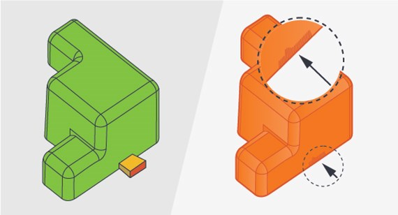
The most commonly used (and largest) gate option is the tab gate. If you were to look at an un-trimmed part, the gate would appear as a tapered rectangle jutting from the part exterior. It’s usually placed where the part is thickest, if possible, and is always placed at the parting line, making it fairly easy to trim and often offering the least impact on part appearance and functionality.
Tab gates are easy to manufacture and maintain, reducing overall costs. Designers typically enjoy a great deal of latitude in gate placement, simplifying mold design. Tab gates also help to confine the stress that’s generated during ejection to the tabbed area, which is trimmed away after molding. In addition, because tab gates are relatively large, they are usually the first choice for use with glass- or mineral-filled resins, which can be difficult to inject through the smaller gates you’ll hear about shortly. For all of these reasons, tab gates are often the first choice among gates.

Hot Tip Gates Reduce Vestiges
Tab gates aren’t perfect, however. They can sometimes leave the largest witness mark, an important consideration for highly cosmetic parts. Second, the runner leading to a tab gate takes up valuable real estate within the allowable mold footprint. This can be a problem if the part pushes the limits of allowable mold size.
Also, the runner leading to a tab gate is kept at the same temperature as the rest of the mold. Since resin cools slightly on its way to the gate, there are potential mold fill considerations like uniformity, concentricity, knit-line formation, challenges with thin features, and so on.

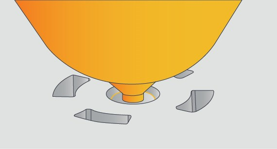
Not so with a hot tip gate. These use a heated nozzle to keep the plastic at its optimal temperature as it flows into the mold—the only vestige is a small round bump, typically 0.060 to 0.080 in. across and 0.010 to 0.020 in. high, which can be trimmed flush to within about 0.005 in. They’re often used with conical or dome-shaped parts to achieve a more desirable radial resin flow rather than the linear flow of a tab gate. For example, if you’re making parts that resemble clear plastic light bulb covers, screw-on lids for food containers, or the palm button used for rolling the dice on a popular board game, chances are good that a hot tip gate is in order.
Other things to consider: Hot tips are positioned near the center of a part rather than at the edge, reducing the distance resin must travel to fill the mold (a good thing) and helping to center press-clamping forces resulting in less equipment wear, mold damage, and flash (more good things). They’re always located on the A-side of the mold, and because this type of gate takes up no space at the edge of the mold cavity, it can be used on parts approaching FacFox’ maximum part footprint size.

And since the resin enters the mold at a higher temperature than with unheated gates, it can travel farther—a factor that’s especially significant with thin-walled part features.
As with all manufacturing processes, however, hot tip gates have their own drawbacks. Depending on part geometry and resin type, they can leave “blush” or flow marks in a circular pattern around the gate site—since hot tip gates are usually positioned on the part’s cosmetic side, this is obviously problematic. Another potential problem is resin degradation, something that occurs when small shot sizes are used and resin sits too long in the barrel. Hot tip molds cost a bit more, although this is easily outweighed by improved part quality. And finally, because it is a small gate, a hot tip can become plugged if used to inject resins with high glass-fill additives—in this instance, a tab gate is generally the best option.
Pin Gates are Geometry- and Material-Dependent
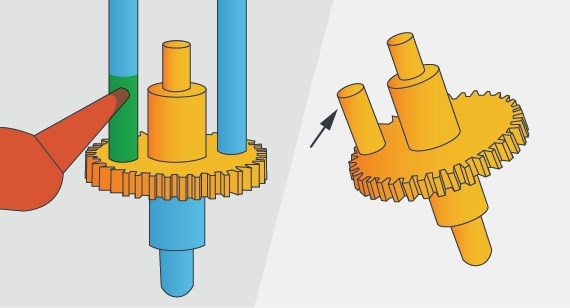
There’s a third type of gate, one that can produce excellent results but is challenging to manufacture. Pin gates—also called post or tunnel gates—are typically used for parts that cannot have gate vestiges on either the parting line (as with tab gates) or on the cosmetic side of the part (where hot tip gates are located). Accordingly, these gates also work well for cosmetic parts. Of the three types of gates used at FacFox, it is the only one found on the B-side of the mold, normally a non-cosmetic surface.
How do they work? As the name implies, pin gates inject resin into the mold via a cone-shaped hole that intersects that is used by the ejector pin. Once the plastic has hardened, the ejector pin does its job, kicking the part out of the mold while simultaneously shearing away the small bit of material left in the gate. The remaining vestige can then be removed manually to within 0.005 in. or more above the part surface, depending on the surrounding geometry and ease of fitting in clippers to snip off the post. One other issue to consider: Having a large post of material made could lead to a sink mark on the A side opposite of the post.
As with many aspects of mold design, the use of pin gates is both geometry- and material-dependent. The shape and size of the ejector pin (and therefore the channel it rides in) may make glass-filled and “slow-flow” resins problematic. The shearing that occurs during ejection can place significant stress on the mold, while the angle and depth of the cone rules out its use with many part geometries such as housings or other cored-out parts. These gates are also common on gears to avoid a tab gate that cannot be used on the outside perimeter of the part.
Clearly, when designing for injection molding, gate selection may require some deliberation. Assuming you haven’t specified one, FacFox will choose the most appropriate gate type and position based on your design and resin, but you will have an opportunity to review gate placement during order confirmation.
As always, if you have questions or concerns, feel free to contact one of FacFox’ applications engineers at info@facfox.com to discuss options.