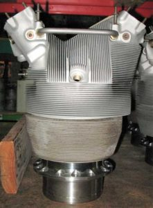
A DC-6 engine from WWII had very involved geometry including hundreds of proximate narrow cooling fins and internal features, the heavy-duty extant cylinder heads were too warped and damaged to function so they decided to reverse engineer new parts using 3D scanning.
“In the past we have used surplus, reworked, or used parts, now we make our own as the need arises—many items are not as plentiful as in the past.”
The Company:
The company is known for repairing, overhauling, and restoring radial aircraft engines of World War II vintage for cargo fleets, fire fighters, militaries, nostalgia operators, collectors, and museums throughout the world. With many decades in the business, the company’s engineers provide expert workmanship and advanced overhaul equipment to keep radial engines safely in the skies. They have also expanded into parts manufacturing and QEC assembly.
The Challenge:
As is often the case with old engines, available parts may be damaged and in short supply. “In the past we have used surplus, reworked, or used parts,” commented the company’s process engineer. “Now we make our own as the need arises—many items are not as plentiful as in the past.”
For this project, the company was rebuilding a round DC-6 engine and needed many cylinder heads that had very involved geometry including hundreds of proximate narrow cooling fins and internal features. The heavy-duty extant cylinder heads were too warped and damaged to function so they decided to reverse engineer new parts. The process engineer had 2D drawings, but they were somewhat deficient. He noted, “The drawings were not 100% complete. Some elements were missing.”
Also since the parts were fabricated before computers were used in the design process, no three-dimensional CAD data existed. Nowadays, CAD files are used to machine tooling for CNC machines to make new parts, so the company needed accurate 3D CAD data of the very complex cylinder head to move forward. The process engineer had been investigating laser scanning as a means to this end and through a recommendation from a previous customer, they contacted Laser Design.
The Solution:
The customer sent several old cylinder heads to Laser Design to laser scan and create a complete three-dimensional scan of the part. Laser Design engineers used the Laser Design 3D laser scanning system.
Because the laser scanning system projects a line of laser light onto all of the part’s surfaces while cameras continuously triangulate the changing distance and profile of the laser line as it sweeps along, the problems of missing data on irregular surfaces are greatly reduced. The laser line moves back and forth over the part’s surface until the complete area is captured on-screen.
The system measures details and complex free-form geometry so that the object can be exactly replicated digitally. Laser scanners measure articles quickly, picking up to 75,000 coordinate points per second, and generate huge numbers of data points without the need for special templates or fixtures. The resulting point cloud is a comprehensive representation of the part.
This cylinder head project was more complex than initially anticipated. It was discovered that each of the hundreds of cooling fins had minute differences in thickness (as small as 0.010”). Due to the general “beat-up” condition, the fins were also warped and out of alignment. Plus, the complex internal geometry was inaccessible from the outside, so the heads would have to be cut open to scan the insides. To recreate the details of the cylinder head’s complete design intent, a multi-step scanning strategy was developed:
1. Scan the entire outside of the cylinder head from 6 positions (5 hours)
2. Remove outside fins/ribs to scan rib position and contour of shape (4 hours)
3. Cut open cylinder head casting to expose internals (2 hours)
4. Scan internal cut pieces to capture inside holes for gasoline flow, spark plugs, etc. (6 hours)
Total hours for one side 17 hours. Repeat process for other side 17 hours. Total hours for whole cylinder head (approximately 1 week’s time) 34 hours.
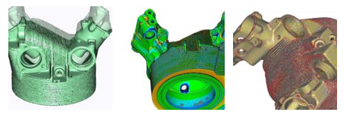
After the 3D laser system scanned the entire cylinder-head, advanced Geomagic Studio software automatically merged the point cloud data from multiple views into a common coordinate system in a single scan file. The data file is smoothed automatically in the sophisticated software package with processing algorithms to remove redundancies and imperfections, and to prepare the data for modeling.
With the complete set of 3D coordinates from laser scanning, the CAD model was created using the accurate point data as a reference model. Left and right halves of the cylinder head were modeled simultaneously since they were symmetrical. Each model was checked and verified against the original scan data to ensure reliable representation of the cylinder heads was generated. The 2D drawings provided a baseline reference from which to compare the data collected in the tiered scanning process and aided in creating the newly minted CAD model. The modeling process took almost 2 weeks, making a turnaround for this complex part just around 3 weeks. The resulting model was an extremely accurate representation of the many details and complex features of the ideal cylinder head design.
Capturing the entirety of the complex geometry of this part would have been virtually impossible without non-contact laser scanning. If manual, touch-measurements methods had been attempted, the 3D coordinates would have been much sparser, taken much longer, and resulted in a much less complete data set that would not have really captured the intricate fins and internal shapes.
The Results:
The resulting high-accuracy 3D data was interpolated into the incomplete 2D drawings to construct a precise representation of the cylinder head’s design intent. Prototype parts will be CNCed and verified to the complete CAD model. Once these parts are approved, the head will go into a production run of about 100, 50 front cylinders and 50 rear cylinders (front and rear cylinders are similar, but not identical).
In the end, the new cylinder heads fabricated from the Laser Design CAD models will be assembled into radial engines that will keep the workhorse vintage aircraft flying well into the future.