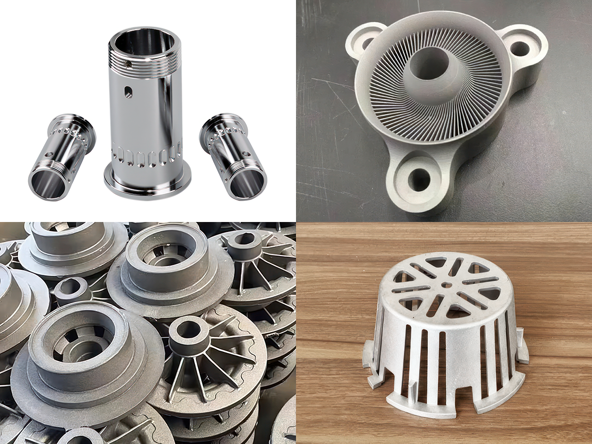
Selecting the right metal manufacturing process is not just about cost or lead time — it fundamentally determines the mechanical performance, surface quality, and long-term reliability of your parts. At FacFox, we offer four core metal manufacturing processes: Metal 3D Printing (DMLS/SLM), CNC Machining, Investment/Sand Casting, and Die Casting. Each delivers distinct material properties, even when using nominally the same alloy.
This article provides a head-to-head comparison of material performance across these processes to help you make informed sourcing decisions.
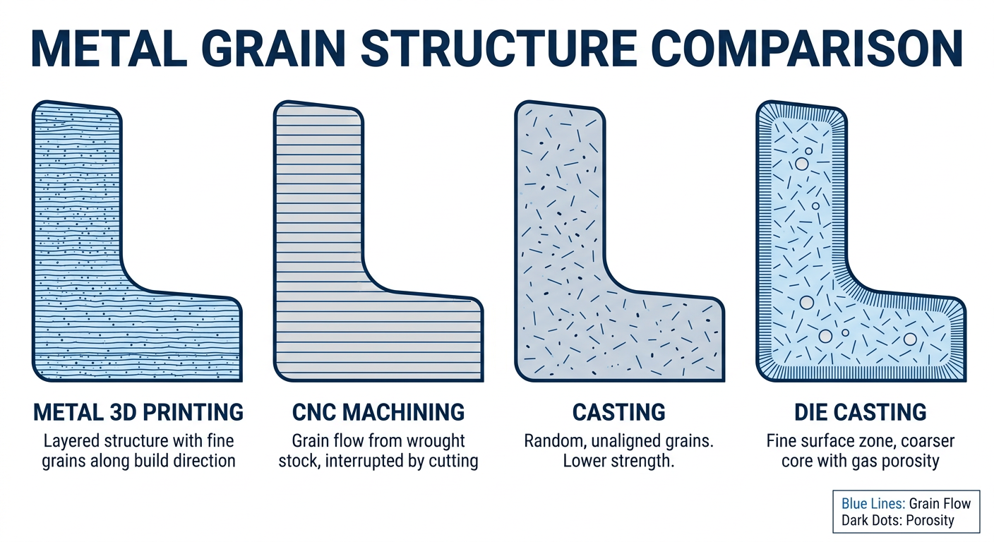
Microstructure and Grain Characteristics
The internal grain structure of a metal part is the single biggest factor driving its mechanical behavior. Different processes produce fundamentally different microstructures.
| Process | Grain Structure | Key Characteristics |
|---|---|---|
| Metal 3D Printing | Fine, columnar grains aligned with build direction | Rapid solidification (10^3–10^6 K/s) creates very fine dendrites. Grain orientation is anisotropic — properties differ between XY-plane and Z-axis. Post-process HIP (Hot Isostatic Pressing) can reduce anisotropy and close internal porosity. |
| CNC Machining | Inherited from wrought stock (rolled, forged, extruded) | Uniform, equiaxed grains from thermomechanical processing. Highly consistent and isotropic. The benchmark for structural reliability. |
| Investment/Sand Casting | Coarse, equiaxed or columnar depending on cooling rate | Slower cooling produces larger grains. Solidification defects (shrinkage porosity, micro-segregation) are common without careful process control. |
| Die Casting | Fine-grained skin, coarser interior | Rapid mold contact creates a fine “chill zone” at the surface with a coarser core. Trapped gas porosity is an inherent limitation of high-pressure die casting. |
Takeaway: CNC parts from wrought stock have the most uniform, predictable microstructure. 3D printed parts are fine-grained but directional. Cast and die-cast parts vary significantly with section thickness and cooling conditions.
Tensile Strength and Yield Strength
Below is a representative comparison using common alloys in each process. Values reflect typical as-produced or standard heat-treated conditions.
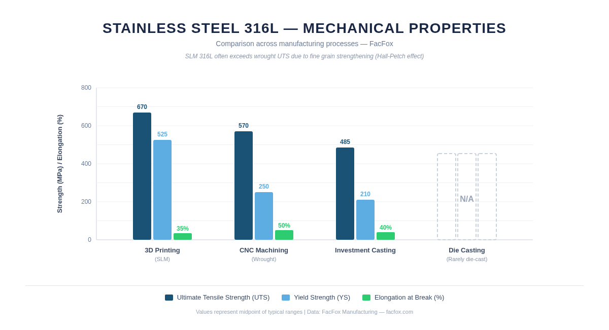
Stainless Steel 316L
| Property | 3D Printing (SLM) | CNC (Wrought) | Investment Casting | Die Casting |
|---|---|---|---|---|
| Ultimate Tensile Strength (MPa) | 640–700 | 515–620 | 450–520 | N/A (rarely die-cast) |
| Yield Strength (MPa) | 500–550 | 205–290 | 170–250 | N/A |
| Elongation at Break (%) | 30–40 | 40–60 | 30–50 | N/A |
Note: SLM 316L often exceeds wrought UTS due to fine grain strengthening (Hall-Petch effect), though ductility may be slightly lower in the as-built condition.
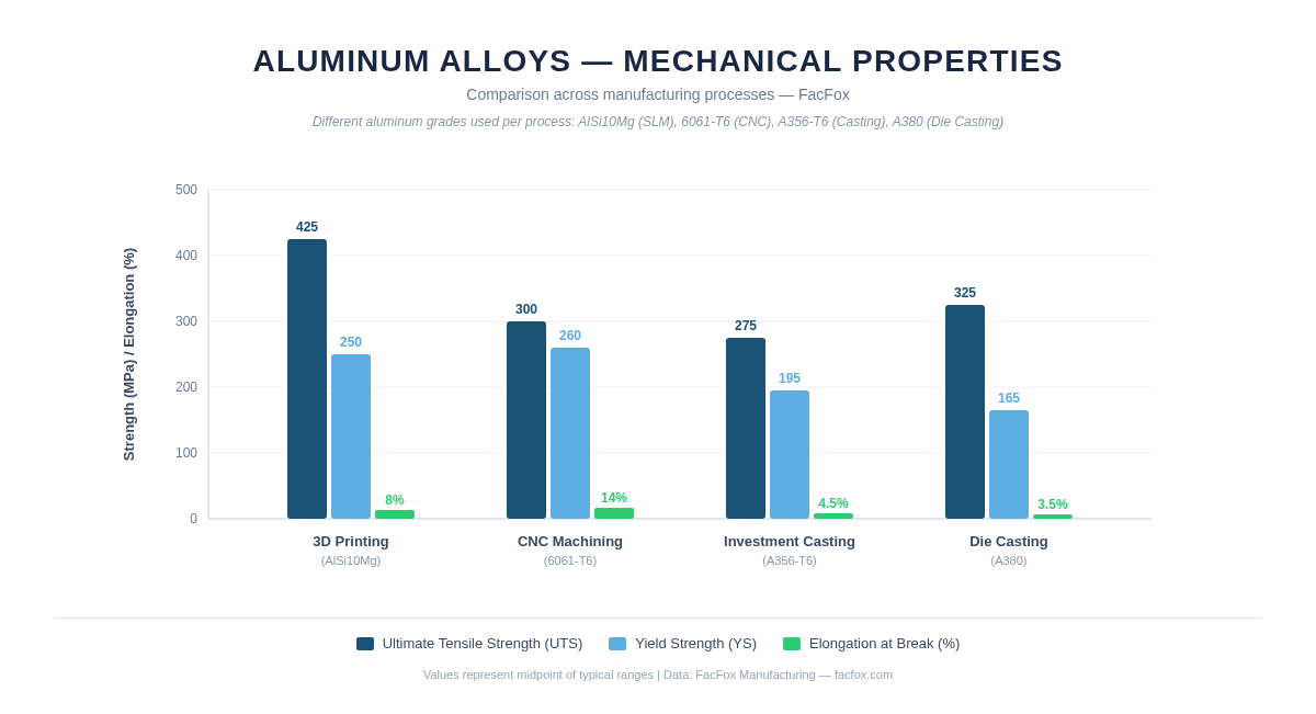
Aluminum AlSi10Mg
| Property | 3D Printing (SLM) | CNC (6061-T6) | Investment Casting (A356-T6) | Die Casting (A380) |
|---|---|---|---|---|
| Ultimate Tensile Strength (MPa) | 400–450 | 290–310 | 260–290 | 320–330 |
| Yield Strength (MPa) | 230–270 | 240–275 | 185–205 | 160–170 |
| Elongation at Break (%) | 6–10 | 10–17 | 3–6 | 3–4 |
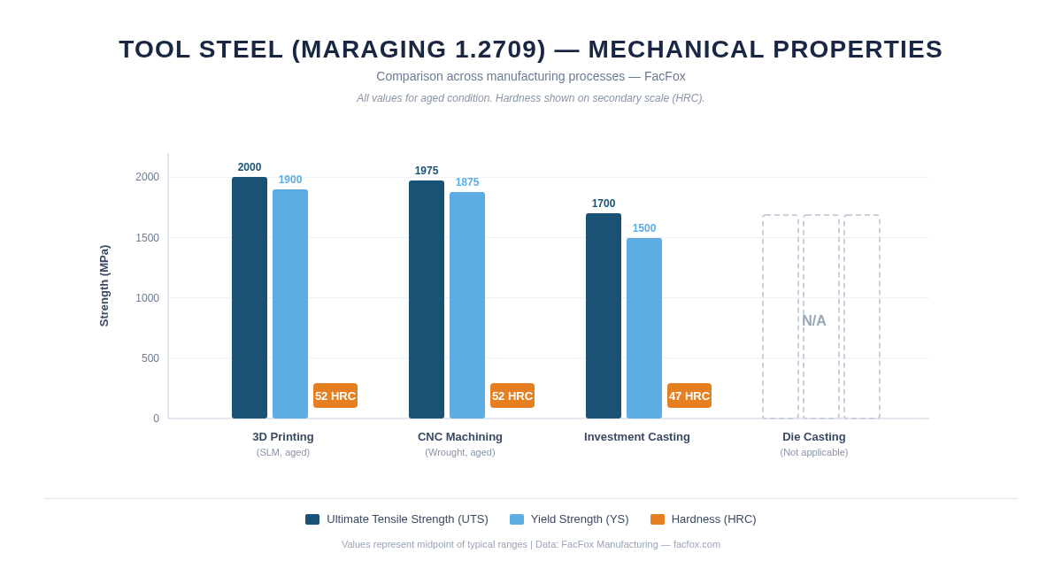
Tool Steel / Mold Steel (e.g., Maraging Steel 1.2709 / MS1)
| Property | 3D Printing (SLM, aged) | CNC (Wrought, aged) | Investment Casting | Die Casting |
|---|---|---|---|---|
| Ultimate Tensile Strength (MPa) | 1900–2100 | 1900–2050 | 1600–1800 | N/A |
| Yield Strength (MPa) | 1800–2000 | 1800–1950 | 1400–1600 | N/A |
| Hardness (HRC) | 50–54 | 50–54 | 44–50 | N/A |
Takeaway: 3D printed metals can match or even exceed wrought strength — especially in stainless steels and tool steels — thanks to rapid solidification. However, CNC parts from wrought stock remain the gold standard for consistent ductility and fatigue life. Castings generally show lower strength unless specifically heat-treated.
Fatigue Life and Fracture Toughness
Fatigue performance is where process differences become critical in load-bearing applications.
| Process | Fatigue Performance | Primary Limiting Factor |
|---|---|---|
| CNC (Wrought) | Excellent — highest and most repeatable fatigue life | Uniform microstructure with minimal internal defects |
| Metal 3D Printing | Good to Excellent (with HIP + machined surfaces) | Internal porosity and rough as-built surfaces act as crack initiators. HIP can close pores; machining critical surfaces is strongly recommended. |
| Investment Casting | Moderate to Good | Shrinkage porosity and inclusions reduce fatigue life. HIP is beneficial but adds cost. |
| Die Casting | Moderate | Trapped gas porosity is difficult to eliminate. Parts generally unsuitable for fatigue-critical structural applications without additional processing. |
Key insight: If your application involves cyclic loading (vibration, pressure cycling, rotating components), prioritize CNC machining or 3D printing with HIP + surface finishing. Standard castings and die castings carry higher risk of premature fatigue failure.
Density and Porosity
| Process | Typical Relative Density | Porosity Source |
|---|---|---|
| CNC (Wrought) | >99.9% | Essentially fully dense |
| Metal 3D Printing | 99.5–99.8% (as-built); >99.9% (after HIP) | Lack-of-fusion defects, gas porosity from powder |
| Investment Casting | 97–99.5% | Shrinkage cavities, dissolved gas |
| Die Casting | 95–98% | Entrapped air from high-speed injection |
Takeaway: Porosity is the hidden enemy of mechanical performance. CNC parts are inherently fully dense. 3D printed parts approach full density with HIP. Castings require careful process control, and die castings inherently contain some porosity.
Surface Finish and Dimensional Accuracy
| Process | As-Produced Surface Roughness (Ra) | Typical Tolerance |
|---|---|---|
| CNC Machining | 0.4–3.2 um | +/-0.025 mm achievable |
| Metal 3D Printing | 6–15 um (as-built) | +/-0.1–0.2 mm (as-built) |
| Investment Casting | 3.2–6.3 um | +/-0.1–0.5 mm |
| Die Casting | 1.6–3.2 um | +/-0.05–0.2 mm |
Takeaway: CNC delivers the best precision. Die casting offers surprisingly good surface finish due to the polished steel mold. 3D printing requires post-machining for tight-tolerance and smooth-surface requirements. Investment casting sits in the middle.
Material Availability
Not every alloy is available for every process. Here is a summary of commonly available metals at FacFox:
| Material Family | 3D Printing | CNC | Investment Casting | Die Casting |
|---|---|---|---|---|
| Stainless Steels (304, 316L, 17-4PH) | Yes | Yes | Yes | Limited |
| Aluminum Alloys | AlSi10Mg, AlSi7Mg | 6061, 7075, 2024, etc. | A356, A357 | A380, ADC12 |
| Titanium (Ti6Al4V) | Yes | Yes | Yes | No |
| Tool/Mold Steels | Maraging, H13 | H13, P20, S7 | Limited | No |
| Copper Alloys | CuCrZr, Pure Cu | C101, C110, Brass | Bronze, Brass | Brass, Zinc alloys |
| Nickel Superalloys (Inconel 625/718) | Yes | Yes | Yes | No |
| Cobalt Chrome | Yes | Limited | Yes (dental/medical) | No |
| Zinc Alloys | No | Limited | Yes | Yes (Zamak) |
When to Use Which Process
Choose Metal 3D Printing when:
- Geometry is complex (internal channels, lattices, topology-optimized shapes)
- Low volume (1–100 parts) or prototyping
- Lightweighting is a priority
- Material is expensive (titanium, Inconel) — additive minimizes waste
- Consolidated assemblies can reduce part count
Choose CNC Machining when:
- Mechanical performance and reliability are paramount
- Tight tolerances and fine surface finish are required
- Material must be fully dense with known, certified properties
- Volume is low to medium (1–10,000 parts)
- Standard shapes (blocks, shafts, housings) are adequate
Choose Investment Casting when:
- Medium complexity geometry at medium-to-high volume
- Near-net-shape reduces machining cost
- Alloys not easily machined (superalloys, cobalt chrome)
- Cost-per-part must be lower than CNC for larger batches
Choose Die Casting when:
- High volume production (1,000–1,000,000+ parts)
- Thin-walled aluminum or zinc parts
- Cost-per-part is the dominant driver
- Structural loads are moderate (non-fatigue-critical)
- Excellent surface finish from the mold is valued
Summary Comparison Matrix
| Criterion | 3D Printing | CNC Machining | Investment Casting | Die Casting |
|---|---|---|---|---|
| Tensile Strength | High | High | Moderate–High | Moderate |
| Fatigue Life | Good (with HIP) | Excellent | Moderate | Moderate |
| Density | 99.5–99.8% | >99.9% | 97–99.5% | 95–98% |
| Surface Finish | Rough (post-process needed) | Excellent | Good | Very Good |
| Dimensional Accuracy | Moderate | Excellent | Good | Good–Very Good |
| Geometric Complexity | Excellent | Limited by tool access | Good | Good (with draft) |
| Ideal Volume | 1–100 | 1–10,000 | 100–50,000 | 1,000–1,000,000+ |
| Cost at Low Volume | Moderate | Low–Moderate | High (tooling) | Very High (tooling) |
| Cost at High Volume | High | Moderate | Low | Very Low |
| Lead Time (first part) | 3–7 days | 3–10 days | 4–8 weeks | 8–16 weeks |
Conclusion
There is no universally “best” process — the right choice depends on your performance requirements, geometry, volume, and budget. At FacFox, we help customers navigate these trade-offs every day. Whether you need the geometric freedom of metal 3D printing, the proven reliability of CNC machining, the cost efficiency of casting, or the scalability of die casting, our engineering team can recommend the optimal path for your project.
Ready to discuss your next metal part? Contact FacFox for a free manufacturability review and quote.