
What is FDM?
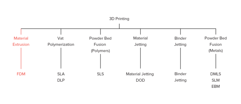
Fused Deposition Modeling (FDM), or Fused Filament Fabrication (FFF), is an additive manufacturing process that belongs to the material extrusion family. In FDM, an object is built by selectively depositing melted material in a pre-determined path layer-by-layer. The materials used are thermoplastic polymers and come in a filament form.
FDM is the most widely used 3D Printing technology: it represents the largest installed base of 3D printers globally and is often the first technology people are exposed to. In this article, the basic principles and the key aspects of the technology are presented.
A designer should keep in mind the capabilities and limitations of the technology when fabricating a part with FDM, as this will help him achieve the best result.
Video: How to prototype like a pro with FDM 3D printing
Here’s a short video that will teach you everything you need to know to get you started with FDM 3D printing in about 10 minutes.
How does FDM work?
Here is how the FDM fabrication process works:
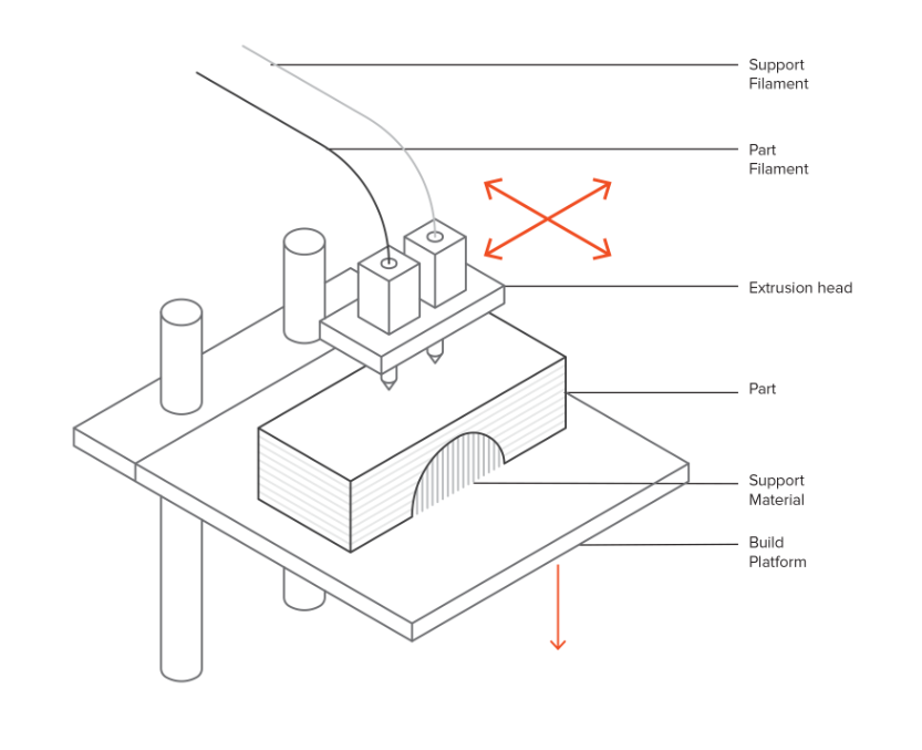
I. A spool of thermoplastic filament is first loaded into the printer. Once the nozzle has reached the desired temperature, the filament is fed to the extrusion head and in the nozzle where it melts.
II. The extrusion head is attached to a 3-axis system that allows it to move in the X, Y and Z directions. The melted material is extruded in thin strands and is deposited layer-by-layer in predetermined locations, where it cools and solidifies. Sometimes the cooling of the material is accelerated through the use of cooling fans attached on the extrusion head.
III. To fill an area, multiple passes are required (similar to coloring a rectangle with a marker). When a layer is finished, the build platform moves down (or in other machine setups, the extrusion head moves up) and a new layer is deposited. This process is repeated until the part is complete.
Characteristics of FDM
Printer Parameters
Most FDM systems allow the adjustment of several process parameters, including the temperature of both the nozzle and the build platform, the build speed, the layer height and the speed of the cooling fan. These are generally set by the operator, so they should be of little concern to the designer.
What is important from a designer’s perspective is build size and layer height:
The available build size of a desktop 3D printer is commonly 200 x 200 x 200 mm, while for industrial machines this can be as big as 1000 x 1000 x 1000 mm. If a desktop machine is prefered (for example for reducing the cost) a big model can be broken into smaller parts and then assembled.
The typical layer height used in FDM varies between 50 and 400 microns and can be determined upon placing an order. A smaller layer height produces smoother parts and captures curved geometries more accurately, while a larger height produces parts faster and at a lower cost. A layer height of 200 microns is most commonly used. An article discussing the impact of layer height in a 3D printed part can be found here.
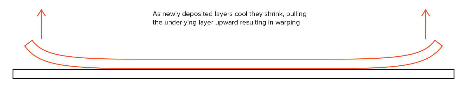
Warping
Warping is one of the most common defects in FDM. When the extruded material cools during solidification, its dimensions decrease. As different sections of the print cool at different rates, their dimensions also change at different speeds. Differential cooling causes the buildup of internal stresses that pull the underlying layer upwards, causing it to warp, as seen in figure 3. From a technology standpoint, warping can be prevented by closer monitoring of the temperature of the FDM system (e.g. of the build platform and the chamber) and by increasing the adhesion between the part and the build platform.
The choices of the designer can also reduce the probability of warping:
- Large flat areas (think of a rectangular box) are more prone to warping and should be avoided when possible.
- Thin protruding features (think of the prongs of a fork) are also prone to warping. In this case, warping can be avoided by adding some sacrificial material at the edge of the thin feature (for example a 200 microns thick rectangle) to increase the area that touches the build platform.
- Sharp corners are warping more often than rounded shapes, so adding fillets to your design is a good practice.
- Different materials are more susceptible to warping: ABS is generally more sensitive to warping compared to PLA or PETG, due to its higher glass transition temperature and relatively high coefficient of thermal expansion.

Layer Adhesion
Good adhesion between the deposited layers is very important for an FDM part. When the molten thermoplastic is extruded through the nozzle, it is pressed against the previous layer. The high temperature and the pressure re-melts the surface of the previous layer and enables the bonding of the new layer with the previously printed part.
The bond strength between the different layers is always lower than the base strength of the material.
This means that FDM parts are inherently anisotropic: their strength in the Z-axis is always smaller than their strength in the XY-plane. For this reason, it is important to keep part orientation mind when designing parts for FDM.
For example, tensile test pieces printed horizontally in ABS at 50% infill were compared to test pieces printed vertically and were found to have almost 4 times greater tensile strength in the X,Y print direction compared to the Z direction (17.0 MPa compared to 4.4 Mpa) and elongated almost 10 times more before breaking (4.8% compared to 0.5%).
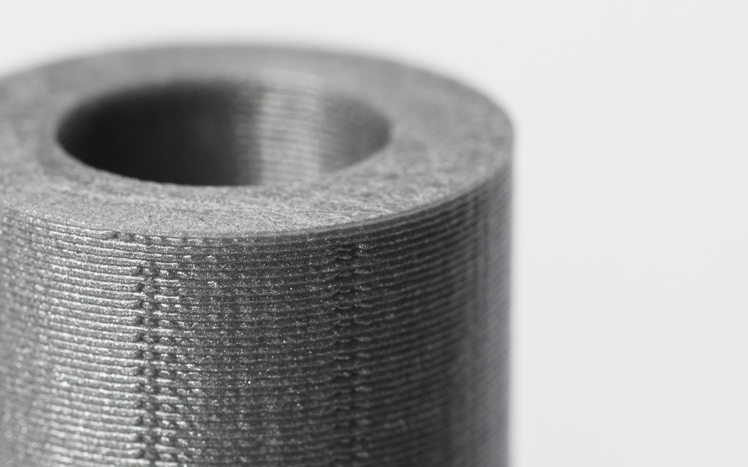
Moreover, since the molten material is pressed against the previous layer, its shape is deformed to an oval. This means that FDM parts will always have a wavy surface, even for low layer height, and that small features, such as small holes or threads may need to be post processed after printing.

Support Structure
Support structure is essential for creating geomentries with overhangs in FDM. The melted thermoplastic cannot be deposited on thin air. For this reason, some geometries require support structure. A detailed article explaining the use of support structure can be found here.
Surfaces printed on support will generally be of lower surface quality than the rest of the part. For this reason, it is recommended that the part is designed in such a way to minimize the need for support.
Support is usually printed in the same material as the part. Support materials that dissolve in liquid also exist, but they are used mainly in high-end desktop or industrial FDM 3D printers. Printing on dissolvable supports improves significantly the surface quality of the part, but increases the overall cost of a print, as specialist machine (with dual extrusion) are required and because the cost of the dissolvable material is relatively high.
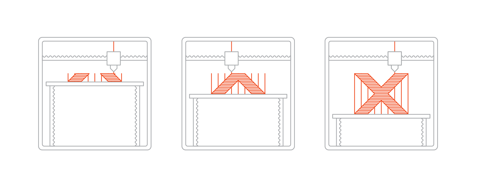
Infill & Shell Thickness
FDM parts are usually not printed solid to reduce the print time and save material. Instead, the outer perimeter is traced using several passes, called the shell, and the interior is filled with an internal, low-density structure, called the infill.
Infill and shell thickness affect greatly the strength of a part. A guide for choosing the best shell and infill parameters for FDM 3D Printing can be found here. For desktop FDM printers, the default setting is 25% infill density and 1 mm shell thickness, which is a good compromise between strength and speed for quick prints.

Common FDM Materials
One of the key strengths of FDM is the wide range of available materials. These can range from commodity thermoplastics (such as PLA and ABS) to engineering materials (such as PA, TPU, and PETG) and high-performance thermoplastics (such as PEEK and PEI).

The material used will affect the mechanical properties and accuracy of the printed part, but also its price. The most common FDM materials are summarized in the table below. A review of the main differences of PLA and ABS, the two most common FDM materials, and an extensive comparison of all common FDM materials can be found in the dedicated articles
| Material | Characteristics |
|---|---|
| ABS |
Good strength
Good temperature resistance
More susceptible to warping
|
| PLA |
Excellent visual quality
Easy to print with
Low impact strength
|
| Nylon (PA) |
High strength
Excellent wear and chemical resistance
Low humidity resistance
|
| PETG |
Food Safe*
Good strength
Easy to print with
|
| TPU |
Very flexible
Difficult to print accurately
|
| PEI |
Excellent strength to weight
Excellent fire and chemical resistance
High cost
|
Post Processing
FDM parts can be finished to a very high standard using various post-processing methods, such as sanding and polishing, priming and painting, cold welding, vapor smoothing, epoxy coating and metal plating. An extensive article on post-processing of FDM parts can be found here
Benefits & Limitations of FDM
The key advantages and disadvantages of the technology are summarised below:
- FDM is the most cost-effective way of producing custom thermoplastic parts and prototypes.
- The lead times of FDM are short (as fast as next-day-delivery), due to the high availability of the technology.
- A wide range of thermoplastic materials is available, suitable for both prototyping and some non-commercial functional applications.
- FDM has the lowest dimensional accuracy and resolution compared to other 3D printing technologies, so it is not suitable for parts with intricate details.
- FDM parts are likely to have visible layer lines, so post processing is required for a smooth finish.
Detailed design guidelines of each of the aspects discussed here are given in later articles of the Knowledge Base. The main characteristics of FDM are summarized in the table below:
| Fused Deposition Modeling (FDM) | |
|---|---|
| Materials | Thermoplastics (PLA, ABS, PETG, PC, PEI etc) |
| Dimensional accuracy | ± 0.5% (lower limit ± 0.5 mm) – desktop± 0.15% (lower limit ± 0.2 mm) – industrial |
| Typical build size | 200 x 200 x 200 mm – desktop1000 x 1000 x 1000 mm – industrial |
| Common layer height | 50 to 400 microns |
| Support | Not always required (dissolvable available) |
Rules of Thumb
- FDM can produce prototypes and functional parts fast and at a low cost from a wide range of thermopalstic materials.
- The typical build size of a desktop FDM 3D printer is 200 x 200 x 200 mm. Industrial machines have a larger build size.
- To prevent warping avoid large flat areas and add fillets in sharp corners.
- FDM is inherently anisotropic, so it is not recommended for mechanically critical components.