HP Multi Jet Fusion (HP MJF) is a powder fusion 3D printing technology that is proprietary to HP. This technology is capable of printing highly complex parts with a high level of precision. To fully utilize the functionality and accuracy of HP MJF, your 3D model has to be designed according to the recommendations. In this overview, you will find the official design recommendations from Hewlett Packard.
Size Limitations
While the maximum build volume is 380 x 284 x 380 mm, the recommended maximum size is 356 x 280 x 356 mm.
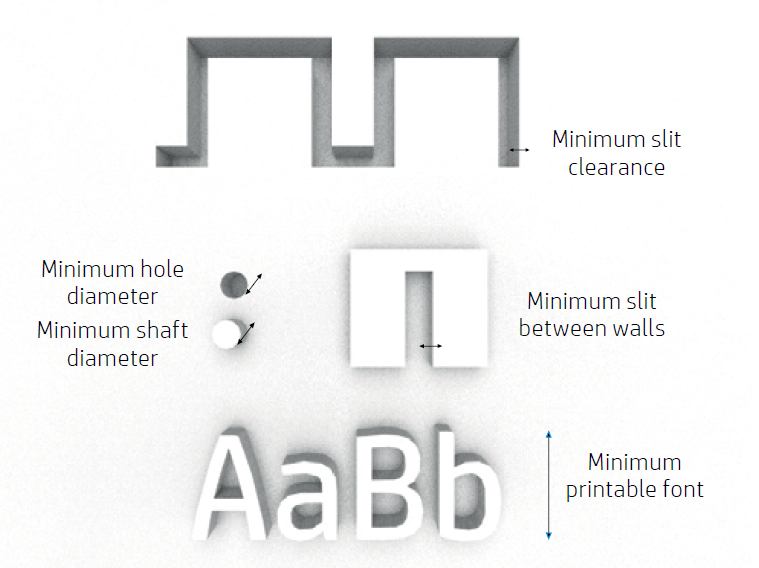
MJF is capable of printing really small parts but there is a limit. The minimum printable sizes for different features in the X, Y, and Z planes are as follow:
- Hole diameter at 1 mm thickness: 0.5 mm
- Shaft diameter at 10 mm height: 0.5 mm
- Font size for embossed and engraved figures: 6 pt
- Minimum clearance at 1 mm thickness: 0.5 mm
- Minimum slit between walls: 0.5 mm
Embossed and Engraved Details
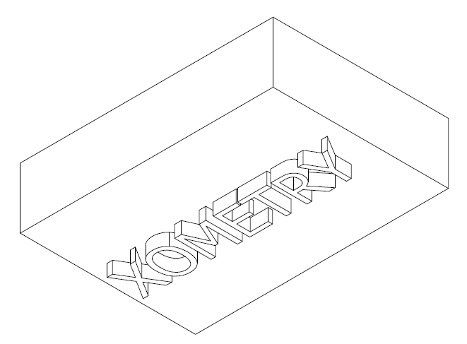
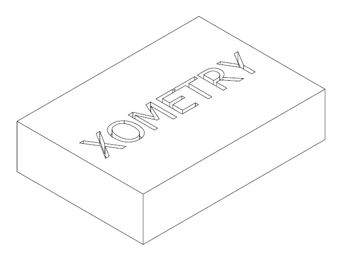
With MJF, you can print high-resolution texts, numbers, and drawings. Any figure included in a part should have a minimum depth or height of 1 mm. This is to ensure visibility and prevent the figure from wearing off during post-processing.
The best resolution is achieved via the upside-down orientations for embossing and facing up for engraving.
Tolerance
HP MJF can print parts with a dimensional accuracy of ±0.2 mm up to 100 mm and 0.2 % above that value. These values are measured after sand-blasting.
Solid Parts and Structural Fill
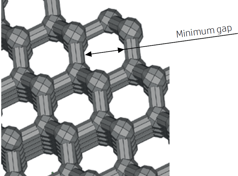
It is possible to print small lattice structures, as well as topology optimized-generative designs using MJF. Such designs help reduce the quantity of material used and the weight of the part. This translates to significant cost saving, especially for weight-sensitive applications.
The recommended minimum gap size in a lattice structure is 1 mm. This is to enable the removal of residual material inside the part.
Walls and Cantilevers
The minimum wall thickness for a cantilever depends on its aspect ratio, which is the ratio of its length to its width. For cantilevers that are less than 1 mm wide, the aspect ratio should be less than one.
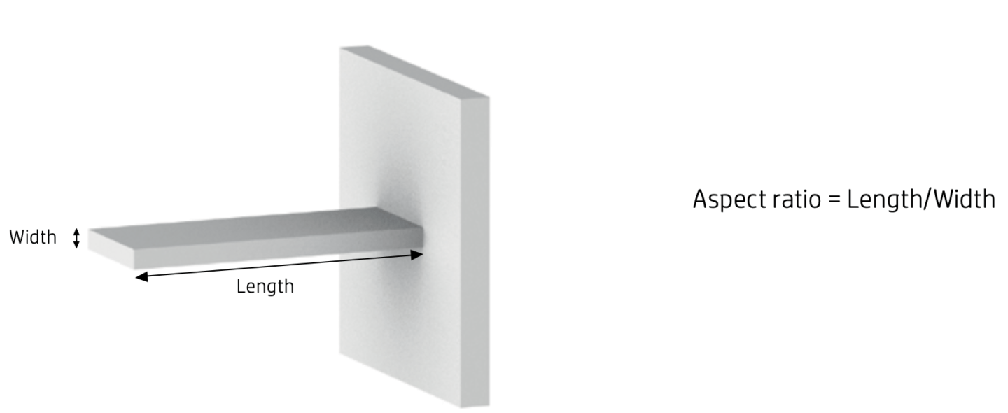
The recommended minimum thickness for short walls in the XY plane is 0.3 mm, and 0.4 mm for short walls in the Z plane. If a high aspect ratio is crucial, increase the wall thickness or add ribs or fillets to reinforce the part. Note that overly thick walls tend to accumulate heat and cause spot shrinkage.

Assemblies
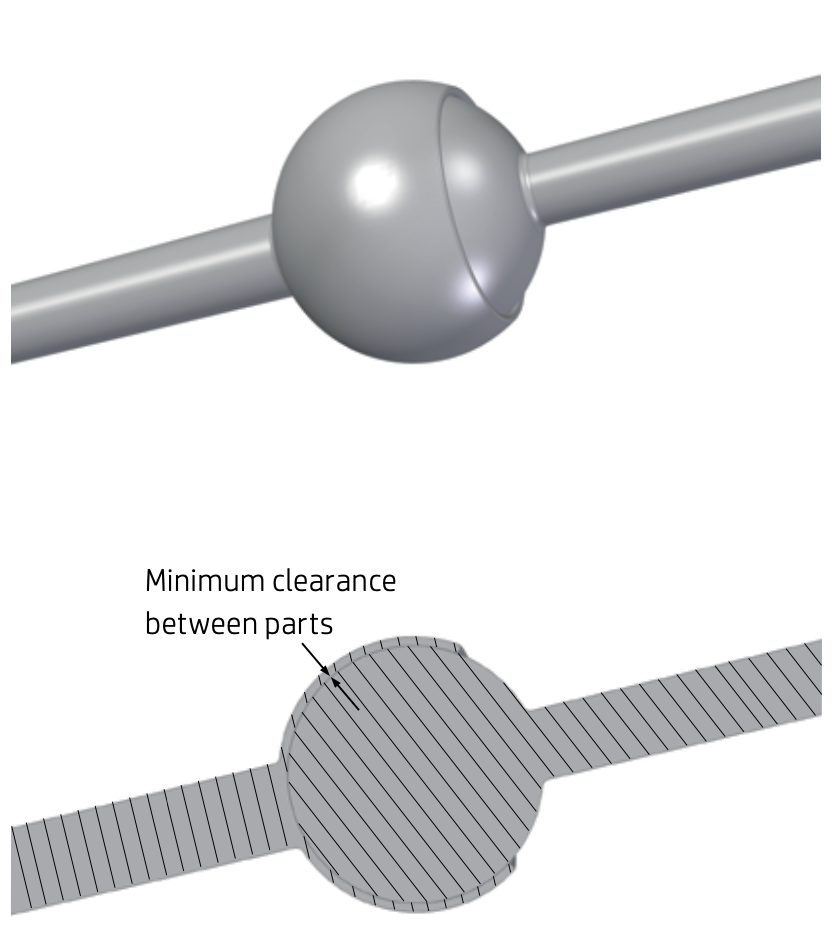
Thanks to its high precision, HP MJF can print fully functional assemblies. Assembly parts that are to be printed together should have a minimum clearance of 0.7 mm to prevent the assembly from fusing to form a single solid part. This value should increase for parts with walls thicker than 50 mm.
For parts that are to be assembled after printing, a minimum clearance of 0.4 mm is required; 0.2 mm for each of the mating parts.
Hollow Closed Parts
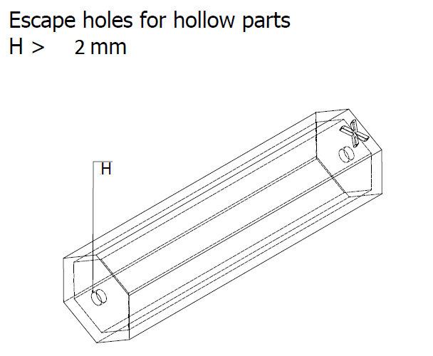
You can print hollow closed solids to reduce part weight and material use. Such parts require at least two drain holes to drain out any residue material after printing. The recommended size of these holes is 2 mm.
Glue Line
Parts that are too big to be printed can be split into different parts and printed separately. The separate parts can then be glued together. If you intend to follow this process, it is recommended that you design interlocking features along the areas of the parts that are to be glued together. This would help the parts bond properly. Additional spaces of 0.1 – 0.2 mm for the glue and the minimum clearance for assembly parts should be added.
Ducts
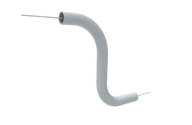
When designing ducts to be printed, consider adding a strip through. After printing, you can simply pull out this strip to dislodge residue powder for easier cleaning.
Part orientation
The orientation in which you should create your design depends on several factors. The following are some of these factors.
- Stepping. Because of the layer-by-layer nature of MJF, a phenomenon known as stepping, in which layers that form a part can be detected, may occur. To avoid stepping in curved or sloped surfaces, it is best to avoid positioning these surfaces at angles that are smaller than certain values, depending on the thickness of the part.
- Accuracy. Features that require high accuracy should be placed in the XY plane as the accuracy of features in this plane is better.
- Warping. To minimize warping, long flat surfaces should be aligned flat with the horizontal plane. Such surfaces should be designed to be as low as possible in the build chamber.
- Smoothness. Curved surfaces which require particularly smooth surfaces should be positioned upside down, while sharp surfaces should face up.
- Load. Features such as clips or pins that need to bear loads should be designed horizontally whenever possible. The best mechanical properties are achieved in the XY plane.