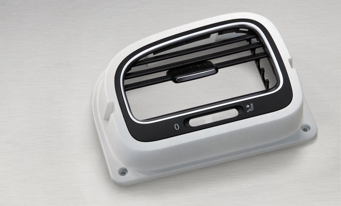
Reverse engineering is a powerful way to create digital designs from a physical part, and can be a valuable tool in your prototyping toolkit alongside technologies like 3D scanning and 3D printing.
3D scanners measure complex objects very quickly, and can speed up your design workflow tremendously when real-life references are involved. With the ability to capture and modify physical shapes, you can design 3D printed parts that fit perfectly on existing products of all kinds. 3D printed jigs allow you to repeatedly locate a drill or saw, or assemble parts precisely with adhesive. Create close-fitting, reusable masks for sandblasting, painting, or etching.
In this post, we’ll walk through the step-by-step reverse engineering process for an aftermarket digital gauge and explain how to scan a part for 3D printing, with tips along the way for using the right reverse engineering tools, from CAD software to 3D scanners and 3D printers.
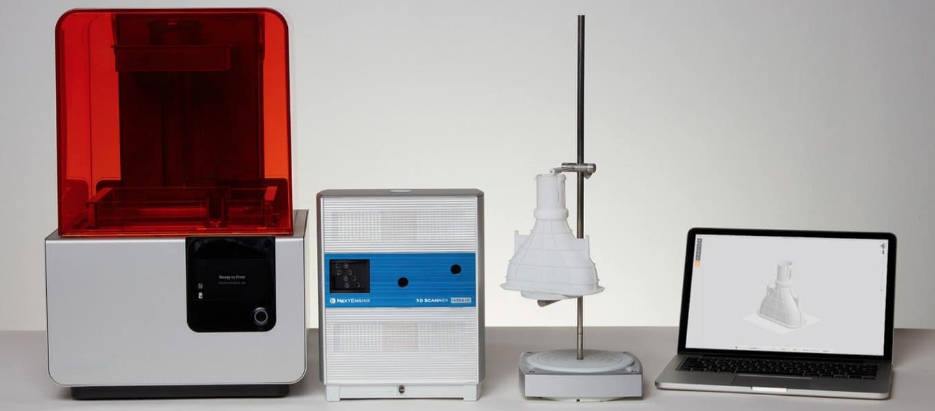
From Physical to Digital: Meshes and Solids
One of the biggest challenges people encounter when converting physical objects to digital is a major incompatibility between two different types of 3D models: meshes and solids.
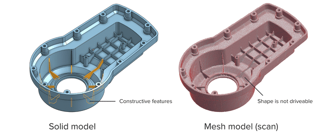
Meshes are the main output of all 3D scanners, and the format commonly understood by 3D printers (STLs). A mesh represents the surface of a shape with a large number of triangles, connected edge to edge. Mesh models don’t contain any information about the object, besides the position of the triangles that define the shape.
On the other hand, engineers are trained to work with solid models. Solid models hold information about how an object is designed, and this information is explicitly encoded into the model as features in a ‘stack’ of logical steps. In solid CAD, it’s possible to change the dimensions for a single feature, and the rest of the model will update to accommodate the change.
Since meshes lack information about the construction of the object, the ways you can alter a mesh model are limited—CAD software like Solidworks and Onshape can’t directly modify meshes. If you need to make major modifications to the underlying design of a scanned part, the mesh needs to be converted to a solid CAD drawing: this process is reverse engineering.
How to Scan an Object for 3D Printing: The Reverse Engineering Workflow
Reverse engineering is important when you want to create new parts that reference or incorporate older designs, where the original CAD design isn’t accessible.
For example, you can create replacement parts that match the original design of damaged existing pieces, or use reverse engineering processes to integrate complex surfaces from existing objects into 3D printable jigs, which are useful when modifying mass manufactured and handcrafted products.
To demonstrate the basic steps in a reverse engineering workflow, let’s take a look at the process for creating an assembly jig for an aftermarket digital gauge that fits onto the air vent of a Volkswagen Golf.
1. Prepare the Object for Scanning
Spray coat the object with a temporary matte powder to improve scan accuracy. Even slightly glossy surfaces tend to degrade scan quality, while reflective and transparent surfaces cannot be scanned at all without a matte coating.
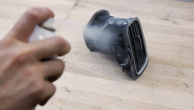
2. 3D Scan the Object
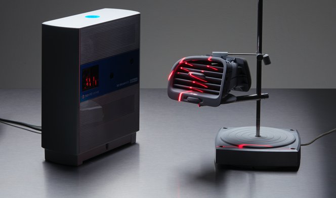
Use a high accuracy 3D scanner to capture the important sections of the part. Tabletop structure light or laser scanners are the right tools for the job, with an accuracy of ±100 or better.
3. Refine the Mesh
Some scanners produce extremely large mesh files, which will make later steps grind to a halt.
Scanner software repairs small gaps and simplifies the scan, making the data more manageable in CAD. Try to reduce the model as much as possible without destroying important details.
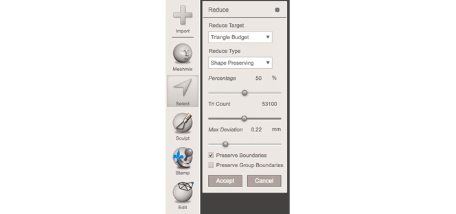
Tip: If you need more control, Meshmixer is a great choice for refining scanned meshes.
4. Import the Mesh to CAD
Import the mesh into CAD software equipped with reverse engineering tools. Geomagic for Solidworks is a powerful choice for resurfacing complex, organic shapes.
If you are reverse engineering a part with simpler flat surfaces, Xtract3D is a less expensive, lightweight alternative.
In this step, move and rotate the scan mesh into alignment with any existing design components.
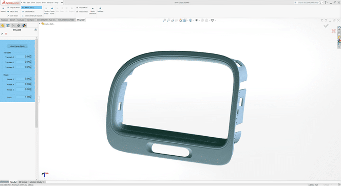
Tip: Make drawing easier by rotating and aligning your scan to face the orthographic view directions.
5. Extract Important Surfaces
There are three paths to extract the shape of the scan in order to create a solid model that is editable with CAD tools: semi-automatic surfacing, automatic surfacing, and manual redrawing.
Semi-automatic surfacing
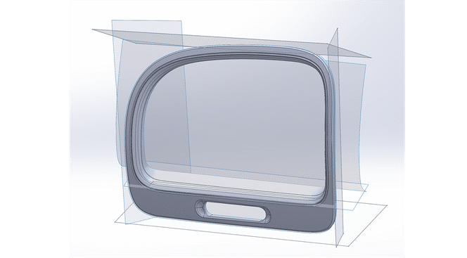
Complex curved surfaces are difficult to manually draw, so you may choose to use semi-automatic surfacing. This function generates surfaces that fit to detected regions of the scan. By varying the sensitivity of the surface detection function, different surfaces will be found.
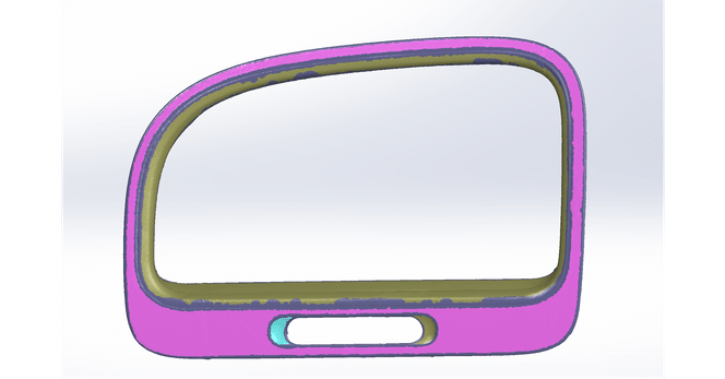
Tip: Geomagic for Solidworks detects surfaces on the scan to fit 3D curves. Use a “brush” to manually add or subtract areas on the scan from each region.
You may need to repeat this process several times with different sensitivity settings to detect all your surfaces. These surfaces can then be trimmed and knit together to create an editable solid.
Use semi-automatic surfacing to re-create curved shapes when you want maximum editability later on, and when sharp edge accuracy is important.
Automatic surfacing
Automatic surfacing generates a solid model from any watertight scan. You can use standard CAD tools to subtract and add to this auto-surfaced body, but it will be more difficult to move basic features around on the body itself.
You may not need control over edge placement. For example, if you are scanning a part of the human body to create custom ergonomically-shaped products, or want to create a jig to precisely or repeatably modify a handmade object. In these cases, automatic surfacing is a great way to save modeling time.
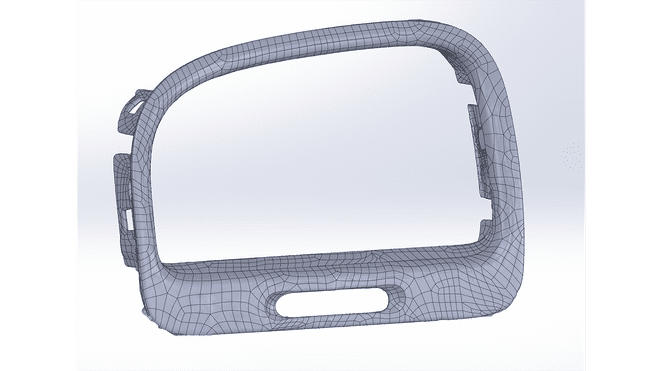
Note: Compare the results of automatic surfacing to semi-automatic surfacing: some accuracy is lost, especially around sharp edges.
Manual redrawing
For simple features such as bosses, holes, and pockets, it’s usually the fastest and most accurate to redraw the features using the scan model as a reference. Reverse engineering software allows you to create sketch planes aligned with flat surfaces on the scan and to extract cross-sections from the scan mesh, which helps you match the shape of the original object.
6. Integrate New Objects
Once the scan has been converted to a solid, it can be subtracted from another solid body to create a jig that securely holds the original part.
The design of the new gauge component also references the dimensions of the scan, using curves extracted with the semi-automatic surfacing.
7. 3D Print the New Design
Printing the jig on FacFox gives you a high degree of accuracy comparable to the output of engineering-grade 3D scanners. Use SLA Tough Resin and SLA Black Tough Resin for its strength and precision.
Once these steps are complete, the 3D printed jig is ready to use to assemble the new gauge onto the OEM air vent.
