Assembly is the process by which part samples (belonging to the same assembly standard (RFC)) are connected to one another. Assembling two basic parts always results in a new, larger composite part that can be used in future assemblies.
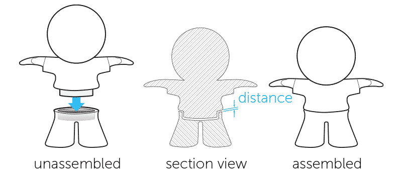
3D printing provides a new solution by enabling people to create parts both through subtractive and additive manufacturing methods. Producing moving assemblies with many articulating components working together has become faster and easier. However, here is an essential tip that you may ignore when designing assembly in 3D CAD: leave enough distance between the parts that will be attached together.
What is the air gap and why it’s necessary?
A green hand may simply create overlapping geometries in the same area, and the 3D printer will print the two or more parts together as if they were one component. Or, he may realize the problem and design a negative space between all parts in the assembly, but forget to leave air gaps between the contact surface.
Please keep in mind that a perfect fit in your software package does not mean a perfect fit after printing. The air gap is a must as your software ignores the friction present in the real world.
How much tolerance should be reserved when designing assembly parts?
A good rule of thumb is that the air gaps should be at least double the layer thickness of your choice, which can be specified before the print.
This allows the gap to be small enough to be unnoticeable at first glance but large enough to allow the soluble support material that fills the gap during the printing process to be washed away by the bath post-print.
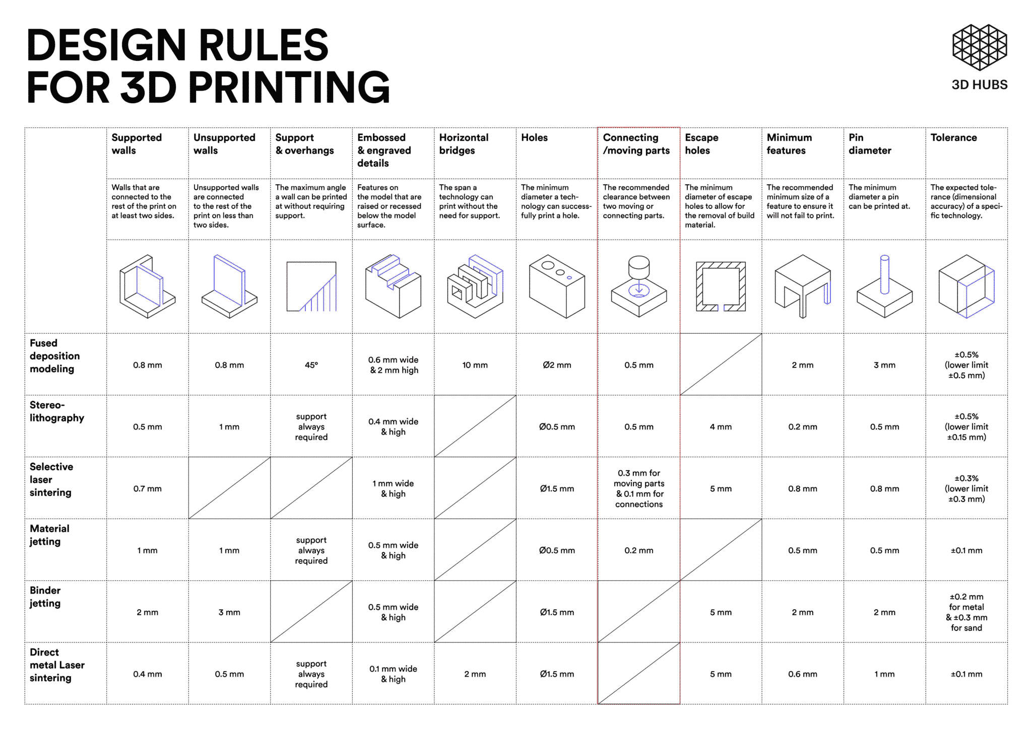
In general, at least 0.3 mm should be left between the different parts. For different 3D printing methods and different structures, however, the necessary tolerances are not the same. Keep the below infographic near you while designing connection and moving parts and use it as a quick reference.
One additional note: 3D printing is bilateral in tolerances (+/- X), whereas other machining operations can be set to unilateral tolerances (+X, -Y). In other words, the reserved air gap of 3D printing parts should be double of tolerance for machining parts.
Taking the coating thickness into consideration
The thickness of the coating of your prints may also result in a failure when assembling. First, you should ensure whether the coating is needed. Mock-up samples usually require no painting on the attached surface as they are made for testing purposes. The exhibition models are better looking with an evenly coated surface.
What kind of coating materials you use also matters. If you want to apply some UV-protection oil, the air gaps should be wider.
Example: Design an FDM 3D printed wrench
I chose to model and print an adjustable wrench with a layer thickness of 0.005”, which is the smallest possible option.
To leave the appropriate amount of space between parts, I needed at least a 0.01” air gap (0.005” * 2) between all of my adjustable wrench’s component faces. This way, there is no risk at all that the extruded paths of the FDM printer will melt together while printing.
One could argue that with all the different possible materials and printing types that are out there, the air gap could increase or decrease from this rule of thumb. While true, using the practice of doubling the air gap compared to the layer thickness of the 3D printed assembly will work as intended in most situations.