Selective laser sintering (SLS) is a powder bed fusion 3D printing technology that uses lasers to create highly accurate parts from powder material. To fully utilize the capabilities of this technology, it is important that your 3D model is designed according to a number of recommendations.
The following are some design tips that would optimize your design for SLS 3D printing.
Size limitations
The consideration of size limitations is very important when designing for SLS 3D printing. The following are some of the size limitations in these technologies.
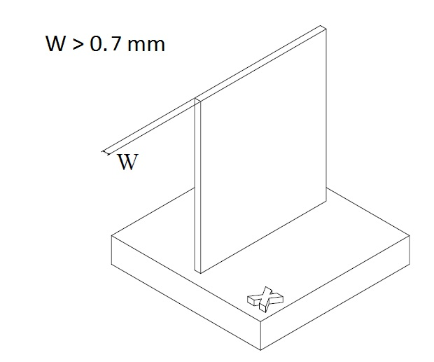
Wall thickness: To prevent collapse during printing or breakage during post-processing or use, it is necessary to design parts with sufficiently thick walls. The recommended minimum wall thickness is from 0.7mm (PA 12) to 2.0mm (carbon-filled polyamide) for SLS. It’s possible to have walls as thin as 0.6 mm, provided a support structure is provided. For either process, a wall thickness of 1.3 mm is preferred for repeatable results, and in most cases, walls do not need to go beyond 4 mm.
Walls thinner than 0.5 mm are likely to over-thicken as a result of the heat from the laser.
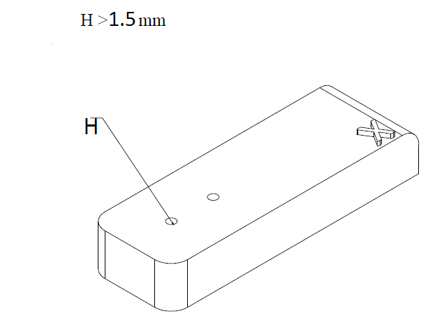
Hole size: The SLS technology can print holes directly in parts (rather than drilling holes after printing. However, the holes you design must not be smaller in diameter than 1.5 mm. This is to prevent unsintered powder from getting stuck in the holes. It is recommended to design holes to standard drill sizes in case they need to be mechanically opened.
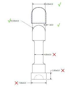
Part size: The maximum printable part size for SLS is 340 x 340 x 605 mm, but we recommend a maximum size of 320 x 320 x 580. The recommended minimum feature size is 0.75, although features as small as 0.5 mm are printable.
Tolerancing
When designing for SLS 3D printing, limit tolerances to areas where they are important such as mating parts. Excessive tolerancing would only increase the printing effort.
Achievable dimensional accuracy depends on the printer and the size of the printed part. SLS is capable of printing with a very high accuracy of up to ±0.3% of feature dimensions (min. 0.3 mm).
Hollow parts
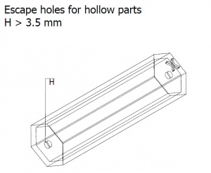
To reduce weight and material use, parts can be designed hollow. For such parts or features, escape hole(s) must be included for the removal of residual unsintered powder from the hollows. The recommended minimum size of the hole(s) is 3.5 mm. Sufficiently large holes are also necessary to allow the interior of hollow parts to be polished via media tumbling.
Interlocking parts
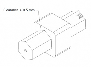
SLS can print mating and moving parts in a single build. This means that using this 3D printing technology, you don’t need to print separate parts before assembling them as you build entire functional assemblies in one cycle. For interlocking parts, models must be designed with a minimum clearance of 0.5mm, with larger clearance preferred if possible. This is to ensure the thorough removal of excess powder to ensure that printed assemblies do not become one solid part.
Engraving and Embossing
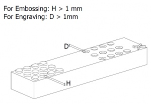
Certain details of parts are engraved or embossed during printing. For such details to be visible, we recommend designing them with a minimum depth or height of 1 mm. This depth is also important for post-processing as any engraving or embossing less than 1 mm may wear off during media tumbling.
Texts can also be printed on parts using SLS. To ensure readability, texts should have a minimum height of 2 mm. Also, the Sans serif font is recommended not only for legibility but also to reduce details. Adding draft to text can help assure that more fragile letters, like the lowercase letter “i” will withstand post-processing and handling.
Warping
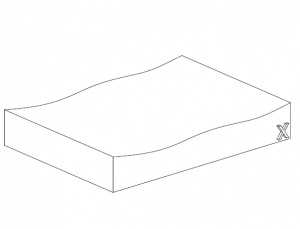
One of the most important design tips for SLS 3D printing is to avoid large flat surfaces. Such surfaces are susceptible to warping and should, therefore, be avoided. If they are a crucial feature of a part, ribs should be included in the design to provide support. Note, however, that this may not always solve the problem, hence, Large flat surfaces should be avoided whenever possible.
Conclusion
Following these tips, you can rest assured that your 3D printed parts would be flawless. Have your designs ready? Head over to our Auto Quote to upload them and get a quote in seconds.