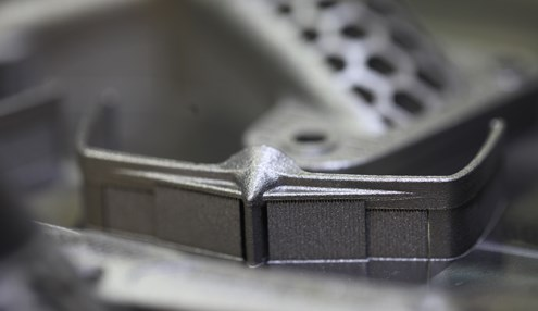
Direct Metal Laser Sintering (DMLS) is the most widely used 3D printing process for delivering fully dense metal parts and components. DMLS is an additive manufacturing process that consecutively melts designs in layers. When beginning a project for DMLS 3D printing, it’s important to remember a few key facts regarding design to ensure you’re optimizing your part for the process.

Support Structures
DMLS is a powder-based 3D printing process, however unlike its plastic counterpart Laser Sintering, DMLS requires support structures which must be removed during post-processing. Support structures are required in most 3D printing processes. Support material is sometimes the same material as the final build, as with DMLS, or separate specially formulated material for easy release from the final part. Support structures are required during printing for a variety factors, either to ensure accuracy while a part completes the curing or hardening process or to maintain tolerances and shape for delicate features. In the case of DMLS, once the metal is sintered it becomes denser than the surrounding unsintered powder and can therefore sink through the powder and break off the part or otherwise warp without support structures in place.
DMLS parts can also experience “burn” (melt deformation) when delicate features are left unsupported because DMLS metals are being melted at extremely high temperatures. We recommend that any angle below 45° incorporate supports and that wall thickness (while geometry depending) maintain a ratio of 8:1 between thickness and height.
Inner Features
While DMLS is favored because it can build no-access features, enclosed designs may still require support structures which can become trapped within a part. To eliminate the need for interior features, we recommend incorporating gradations between features. Rather than abrupt feature changes between wall and inner structure, utilize a fillet to gradually shift between features. In the design below, we’ve taken the inner chamber of this design and changed it from a sharp angle in the cross-sectional view on the left (which would have excessive trapped supports) and added a fillet in the middle on the right. The new design configuration on the right won’t require any internal supports.
Updating your design to account for supports structures and delicate features will ultimately result in a better overall build with DMLS. In turn, a better-designed part will be stronger after undergoing heat treatments and other strengthening post-processing treatments. You can learn more about the heat treatments we use on DMLS parts, including HIP and SHT, through our white paper “Getting the Most out of Metal 3D Printing”.
DMLS is an invaluable asset for complicated designs machining and casting cannot easily achieve. Check out DMLS materials available to you on our materials page or contact a project engineer to learn more at info@facfox.com.