3D printing is a revolutionary way to create custom geometry, but it faces a fundamental engineering challenge: mechanical fasteners in plastic are weak. If you screw a bolt directly into a printed part, the plastic threads will strip, creep, or fail after just a few assembly cycles.
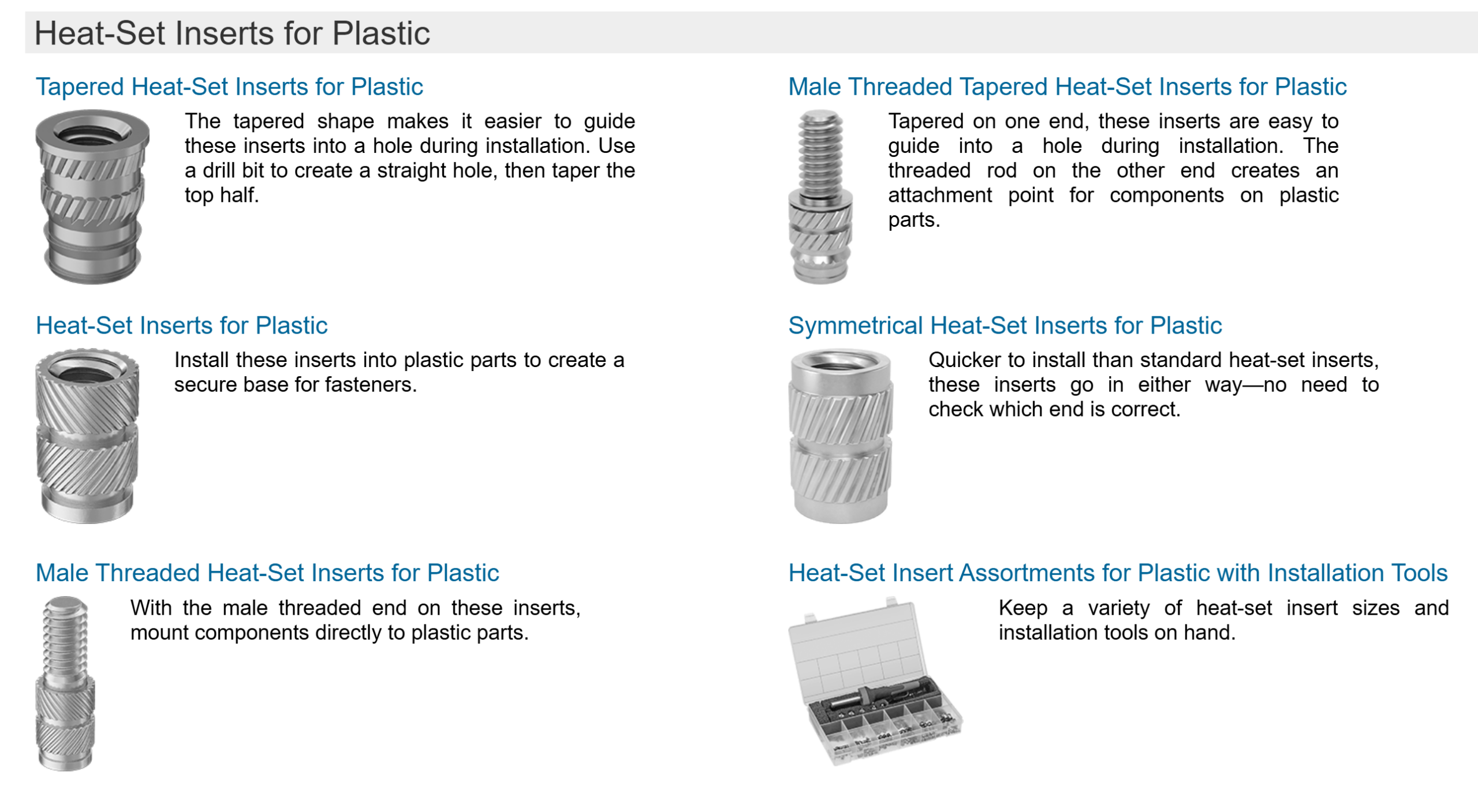
For professional-grade projects, heat-set inserts are the gold standard. They provide the wear resistance of metal threads with the lightweight flexibility of 3D printing. Based on industry best practices from CNC Kitchen and Markforged, here is a comprehensive guide to mastering heat-set inserts.
1. The Engineering “Why”: Inserts vs. Alternatives
Before reaching for the soldering iron, it’s important to understand why inserts are usually the right choice:
-
Longevity: Unlike tapping threads directly into plastic, metal inserts allow for hundreds of assembly/disassembly cycles without degradation.
-
Surface Area: The knurled (textured) exterior of an insert provides a much larger surface area for the plastic to grip than a screw thread does. This significantly increases “torque-out” (resisting spinning) and “pull-out” (resisting being ripped out) strength.
-
Heat-Set vs. Embedded Nuts: * Embedded Nuts (pausing the print to drop in a hex nut) offer incredible pull-out strength but are difficult to design and impossible to replace if a bolt snaps inside.
-
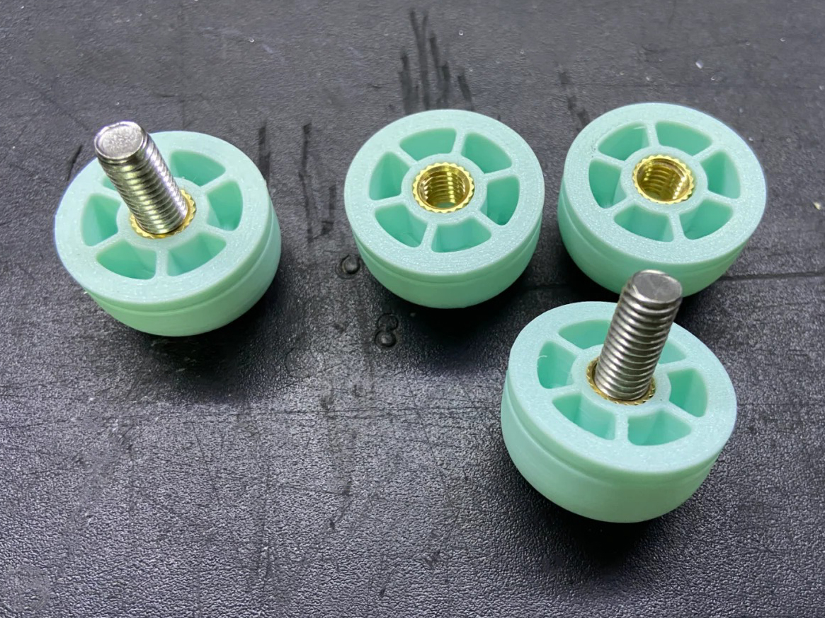
Heat-Set Inserts provide a more professional, flush finish and can be installed post-print, making the workflow much more flexible.
-
2. Design Guidelines (CAD)
The success of an insert is decided in your CAD software, not during installation.
-
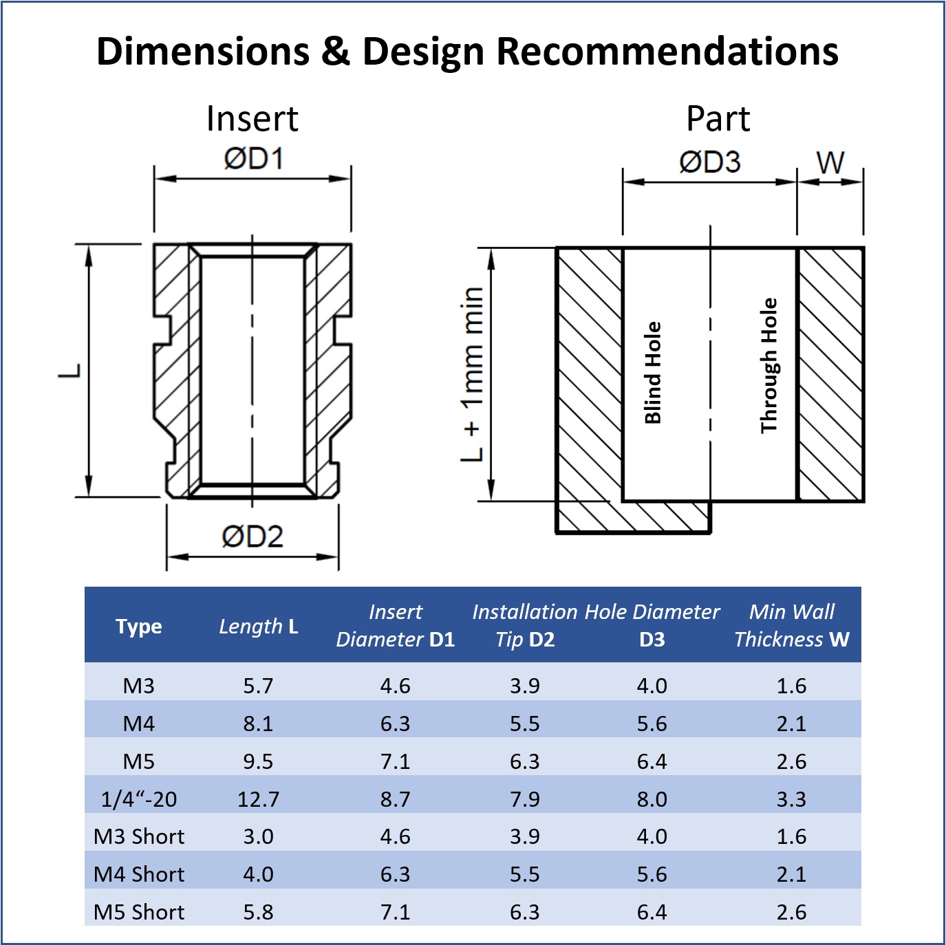
The Tapered Hole: Don’t design a simple straight cylinder. Most professional inserts have a slight taper. Markforged recommends a counterbored hole with a major diameter (at the top) and a minor diameter (at the bottom) to guide the insert and provide a “well” for displaced molten plastic.
-
Wall Thickness: You need enough “meat” around the hole to prevent the plastic from bulging. A rule of thumb is to have a wall thickness at least 2x the diameter of the insert.
-
The Relief Well: Always design the hole about 1–2 mm deeper than the insert. When you melt the insert in, it will push a small amount of molten plastic (a “burr”) downward. Without a relief well, this plastic will clog the threads or prevent the insert from sitting flush.
-
Slicer Settings: Increase your wall count (perimeters). You want the insert to be surrounded by solid plastic, not air-filled infill. 4–6 walls is recommended for structural parts.
3. The Professional Installation Workflow
To get a perfectly vertical and flush result, follow this process:
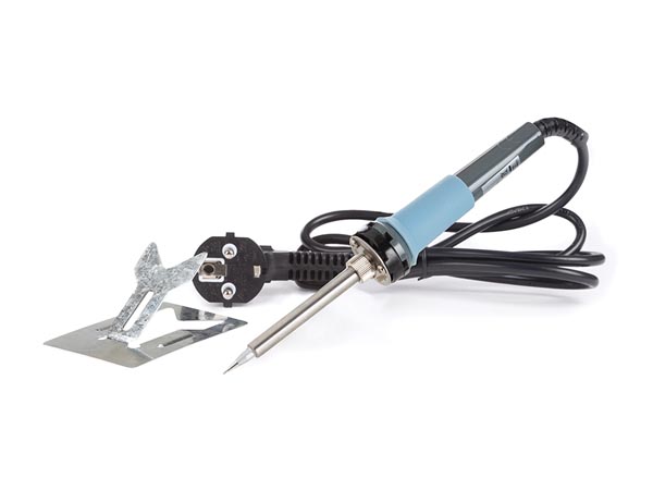
- Tooling: While a standard soldering iron works, use a dedicated heat-set installation tip. These tips are flat and fit inside the insert, ensuring even heat distribution and preventing the iron from slipping and scarring the part.
- Temperature: Set your iron roughly 10–20°C above your printing temperature (e.g., ~230°C for PLA, ~260°C for PETG). You want the plastic to melt, not burn.
- The “90% Rule”: Use the iron to push the insert about 90% of the way into the hole.
- The Flush Finish: Remove the iron and quickly press the insert the final 10% of the way with a flat metal object (like a scraper or a heavy nut). This ensures the insert is perfectly flush and vertical while the plastic is still “living.”
- Cooling: Do not screw a bolt into the insert immediately. Wait 2–3 minutes for the plastic to recrystallize and reach full strength.
4. Advanced Tips & Troubleshooting
-
Load Direction: For maximum strength, design your part so the screw pulls the insert into the plastic (mating on the opposite side). This utilizes the “shoulder” of the plastic to resist the force, rather than relying solely on the friction of the knurls.
-
Resin (SLA) Printing: You cannot “heat-set” an insert into resin because resin is a thermoset plastic (it burns/cracks instead of melting). For resin, you must design a stepped hole and use high-strength CA glue or epoxy to secure the insert.
-
The “Spinning” Insert: If an insert spins when you tighten the bolt, the hole was likely too large or the walls too thin. You can sometimes “save” a part by adding a tiny drop of epoxy, but the best fix is to adjust the CAD for a tighter interference fit.
-
Orientation Matters: Holes printed vertically (Z-axis) are generally more accurate than holes printed horizontally. If you must print a hole horizontally, expect a slight “sag” at the top and adjust your diameter accordingly.
Elevate Your Assembly with FacFox
Precision engineering doesn’t end when the 3D printer stops. At FacFox, we understand that the strength of your final product often relies on the quality of its mechanical connections.
Whether you are developing complex robotics, industrial enclosures, or durable consumer prototypes, our post-processing suite offers professional heat-set insert installation to ensure your parts are ready for the rigors of real-world use. By combining our state-of-the-art 3D printing technologies (FDM, SLS, and MJF) with expert assembly services, we provide a “one-stop shop” for parts that look, feel, and function like injection-molded components.
Ready to build something stronger? Upload your CAD files to FacFox today and let our engineers help you choose the best materials and fasteners for your project.