Introduction
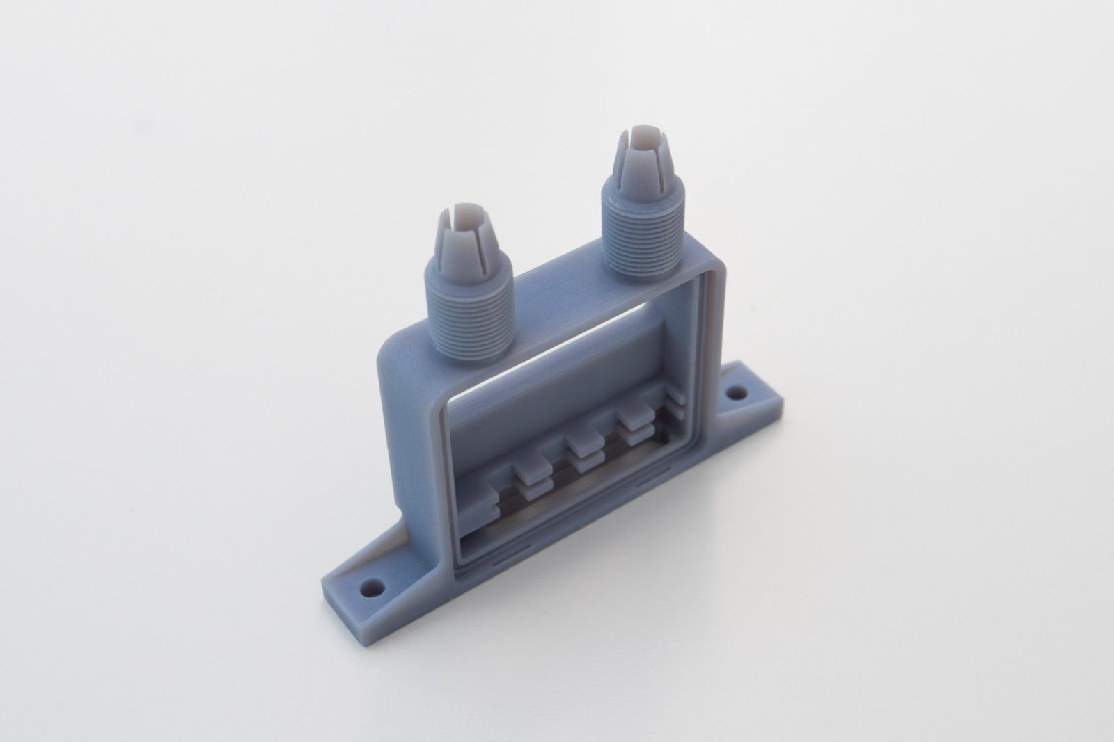
Material Jetting is one of the most accurate 3D printing technologies producing high detail parts with a very smooth surface. With some Material Jetting printers offering full color, multi-material parts, Material Jetting is used regularly to produce realistic prototypes and models. Parts are generally brittle and not used for functional applications.
This article will discuss the advantages of using Material Jetting to 3D print parts, present the most common Material Jetting materials and establish a clear set of design rules for designers to follow when printing with Material Jetting technology.
The Material Jetting process
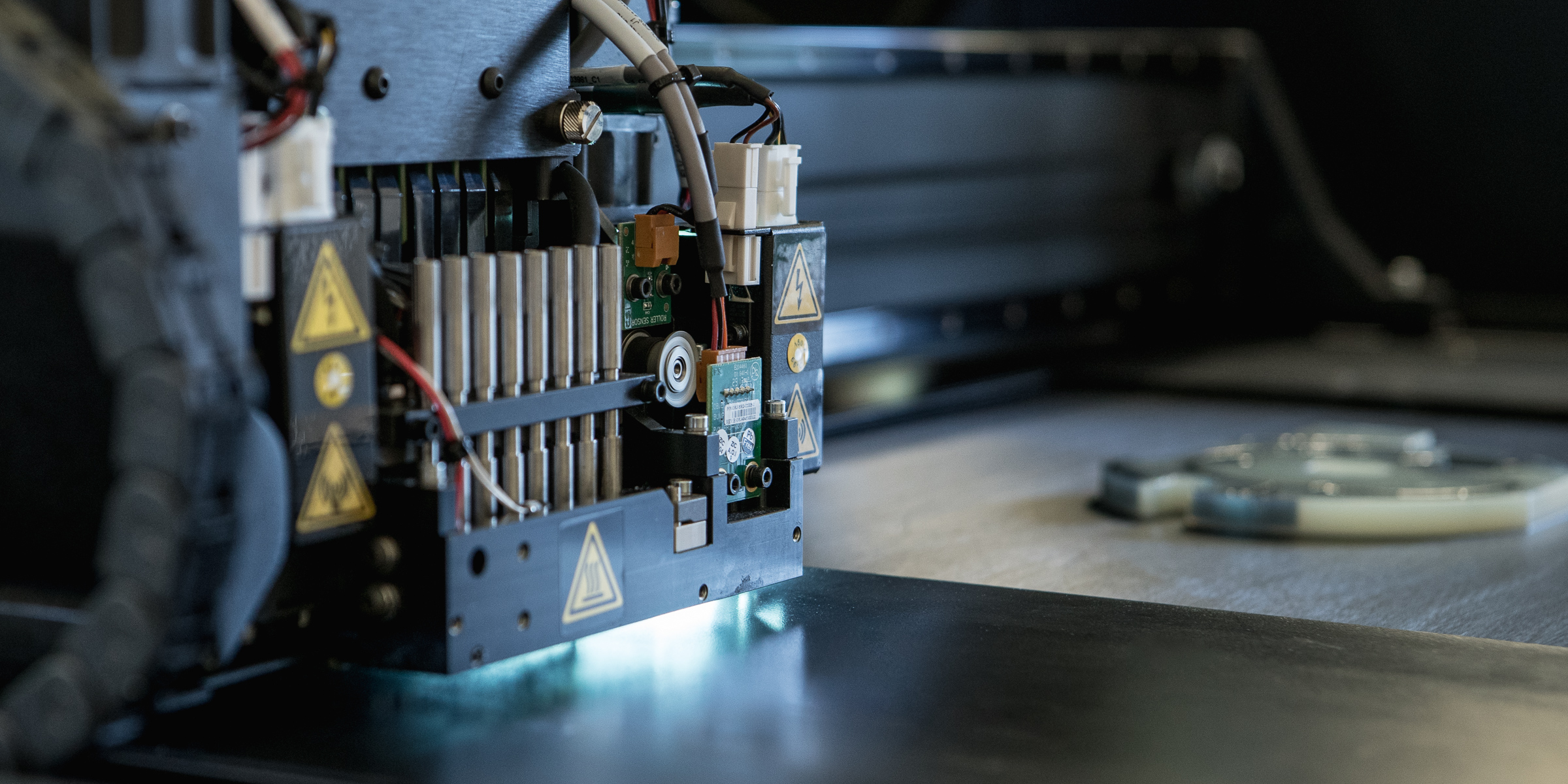
Material Jetting works much like a standard inkjet printer. However, instead of printing a single layer of ink, thousands of layers are built upon one another to create a solid part. Via hundreds of tiny jets, Material Jetting printers dispense a photopolymer over a specific area. The print head then cures (solidifies) the photopolymer via a UV light. After a layer has been deposited and cured the build platform drops down one layer thickness and the process is repeated to build up a 3D part.
Unlike most 3D printing technologies that deposit, cure or sinter build material through point-wise deposition technologies (a single point follows a path to complete the cross sectional area of a layer), Material Jetting operations deposit build material in a rapid, line wise fashion. Because of this, Material Jetting printers are able to print multiple parts in a single line with no effect on build speed. If parts are correctly placed, and the space within each build line is optimised, Material Jetting is able to produce parts at a much quicker rate than other 3D printing technologies.
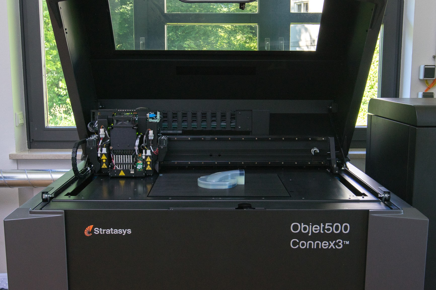
Material Jetting processes require support and this is printed simultaneously during the build from a dissolvable material that is removed during post processing.
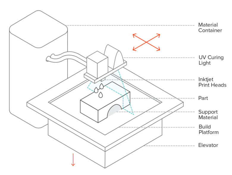
Material Jetting has 2 main advantages over other 3D printing technologies. Firstly, Material Jetting creates a near homogeneous part as the layers are cured throughout the printing process. Secondly, parts produced with Material Jetting have a very smooth surface comparable to injection molded parts. Because of this the technology is specifically for creating realistic prototypes that closely represent end-parts.
The biggest limitations of Material Jetting is that the parts produced have poor mechanical properties and are typically very brittle.
Designing for the Material Jetting printing
The section below outlines several design recommendations when designing parts to be made via Material Jetting.
Print features
| Feature | Description |
|---|---|
 |
Major support walls -The minimum wall thickness for major supported walls is 1 mm. |
 |
All other walls – For all other walls the minimum wall thickness should be no less than 0.5 mm. |
 |
Pin diameter – A minimum pin diameter of 0.5 mm is recommended |
 |
Hole size – For a hole to successfully print the minimum diameter should be no smaller than 0.5 mm. Holes, whenever possible, should be oriented vertically, to maximize the circularity of the feature. |
 |
Embossed and engraved details – To ensure small details are visible the following rules apply:
|
 |
Feature size (pins, protruding features etc.) – Material Jetting is capable of producing part details as low as 0.25 mm. |
 |
Moving parts: Assembled parts, hinges and joints should have 0.15 – 0.2 mm clearance around all sides. This clearance must also be accessible in some way to allow for cleaning/removal of the support material that will build in the gap. |
 |
Tolerances – Tolerances for parts made via Material Jetting range from from +/-0.1mm – 0.3mm depending on geometry and material. |
Common design applications
The following table identifies some of the most common design applications for Material Jetting.
| Application | Description |
|---|---|
| Full colour models | The high level of accuracy, smooth surface finish and colour options make Material Jetting a popular choice for presentation and fit/form models or prototypes. |
| Injection mold prototypes | The surface finish produced by Material Jetting mean it is an excellent choice for showcasing the appearance of injection molded part prototypes before investing in expensive tooling. |
| Injection molds | Material Jetting is regularly used as a method of producing low run injection molds. The high degree of accuracy and smooth surface mean that the molds require very little post processing and are a cost effective solution for production runs less than 100 parts. |
| Enclosures | While Material Jetting parts are often brittle the large range of materials and colors available have seen the technology used for the production of custom enclosures. Snap fit connections are commonly integrated into the enclosure designs as well. |
| FEA models | The multi-color printing ability of Material Jetting means that the technology is able to produce physical FEA models. If an FEA analysis is performed on a part virtually, the resulting colour pattern can be exported as a texture or layer and printed on the part directly, creating a visible FEA colour pattern on a physical sample for review. This offers engineers and designers a unique insight into how a part will perform under load. |
Glossy vs. matte
Material Jetting offers the option of printing parts with either matte or glossy settings. The matte setting will add a thin layer of support across the entire part, regardless of orientation or requirement. The glossy setting will only use support material where required to allow for the building of the model (overhangs, drafts, cavities, etc.).
Glossy: The advantages for printing with a glossy setting are strength on thin walls, aesthetics of a smooth and “finished” part, and reduction in material usage for the build. The disadvantages include a non-uniform finish on parts and some slight rounding of sharp edges and corners on top surfaces.
Matte: The advantages for printing with a matte setting are accuracy of the part as a whole, as well as a uniform finish. Disadvantages include the additional material requirement, the additional cleaning time required, and a softer surface. This softer surface can sometimes lead to weakness in small or thin features.
Dissolvable support
One of the biggest advantages of Material Jetting is that all parts are printed in 2 different materials; one for the main build material and the second as dissolvable support. This means that unlike other 3D printing methods where support must manually be cut away from the part, support is dissolved and easily removed with agitation. When post processed correctly this can result in a surface that shows no indication of support at all.
This also means that part orientation is much more flexible than other 3D printing technologies. This coupled with the relative homogeneity of material jetted parts offers greater design freedom and allows very complex and intricate design so be printed and easily post processes.

Multi-colour printing
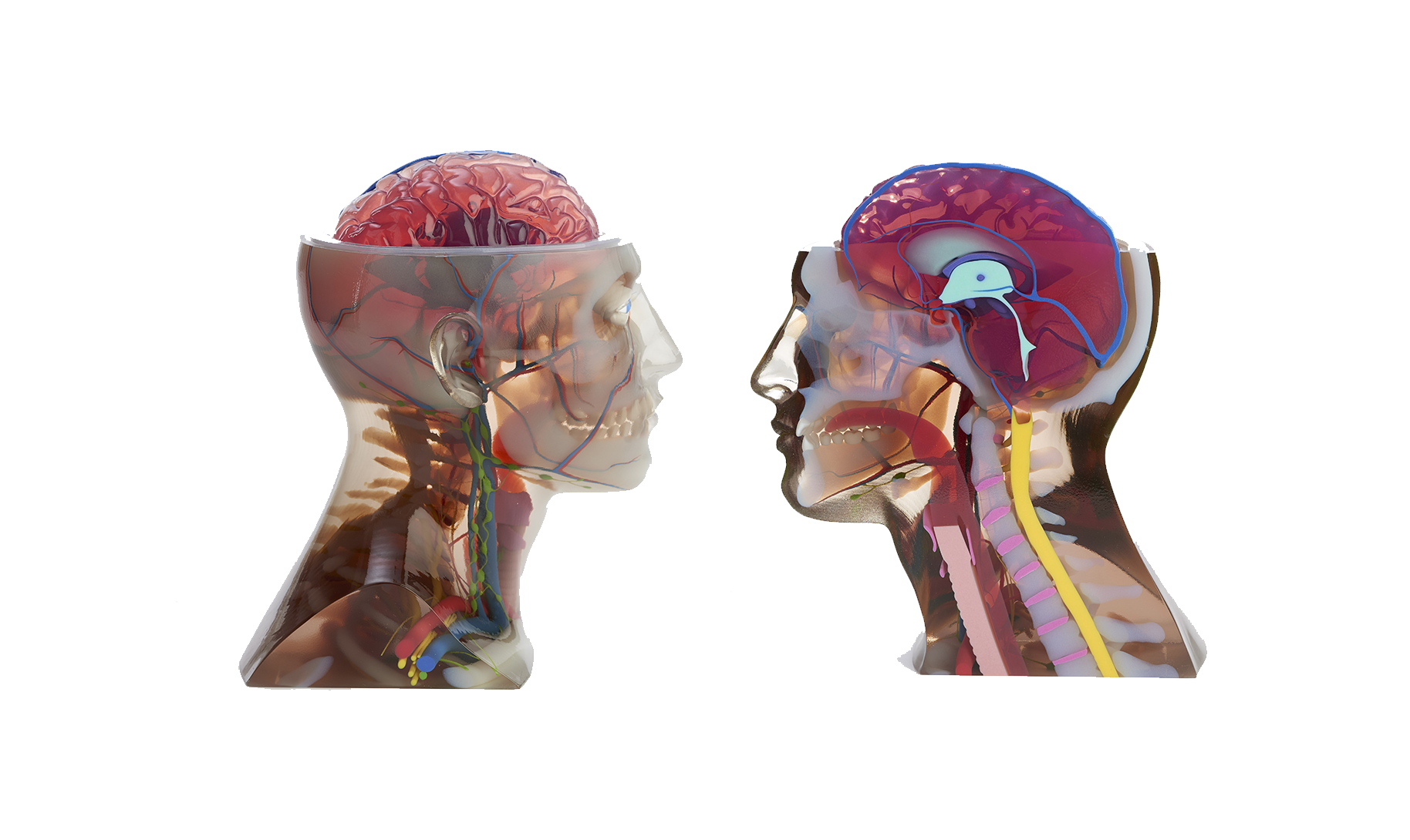
Material Jetting is the only 3D printing technology that is able to produce full, multi-colour prints. By using Cyan, Magenta, Yellow, Black, and White rigid materials (CMYK) a full suite of colour options are available. This can be achieved through the print setup process, by assigning RGB colour codes to the parts, or can be done in the CAD process, by colouring the part, and exporting as a VRML file. Texture layers, such as pattern prints and finishes, can also be applied to the part in CAD, and exported as a VRML. Things like brush strokes, wood grain, and gradient colours, can be added to parts using this method.
The medical industry has taken advantage of this for educational, high detail, anatomical models as shown in the image below.
Multi-material printing
One of the largest advantages to printing with the Material Jetting process, is the multiple material print capabilities. Some machines are capable of printing both rubber and rigid components on the same tray, within the same part, and also as a blend, to form new material properties (a soft rubber like material, and a hard rigid material, can be blended to form a variety of different hardness levels of rubber). When designing for this, it is important to build assemblies in the native CAD, so that the different parts can be selected as the different materials during print preparation. When mating these assembled parts in CAD, there should be no overlap of the bodies. A “0” clearance mate should be used. This will allow the parts to fuse properly. If attempting to build a 2 part assembly, with an opaque material embedded within a clear body, it is important to ensure that there is a negative cavity, corresponding directly with the positive of the internal part. Any overlapping bodies in a CAD model, will be ignored when printing resulting in the area being filled with the main build material.
Material Jetting materials
There are an extensive number of materials available when printing with Material Jetting. All materials are photopolymers and are generally separated by application. The table below presents some of the most common Material Jetting materials.
| Material | Description | Applications |
|---|---|---|
| Standard (rigid opaque) | Rigid, normally opaque materials. Typically available in White, Black, Grey, and Blue. These are generally regarded as Polyethylene (PE) mimics and are brittle compared to some other printing processes. Example materials: Vero, VeroBlue, Visijet M2, Visijet CR, full colour prints | High detail, non functional prototypes and parts with a very smooth surface |
| Transparent | Similar properties to standard however can be post processed to be 100% transparent. Example materials: VeroClear, Visijet M2, Visijet CR | Clear prototypes and models |
| ABS-like | A durable digital blend of materials. This material has a higher temperature range and strength, while also allowing for good flex in features. Requires a minimum thickness on all walls of 0.85mm. Example materials: Digital ABS, VisiJet M3-X | Components that are required to simulate ABS. Parts are more brittle than FDM or injection molded parts. |
| Polypropylene-like | Polypropylene (PP) mimic material, excellent for flex and snap feature. Example materials: Rigur, VisiJet M5 Black | Components that are required to simulate PP. Parts are more brittle than injection molded parts. |
| Flexible | Rubber mimic materials. The blends can be done in such a way that a custom durometer is achieved, ranging from very flexible to nearly fully rigid. The materials focus on mimicking the feel and flex of rubber and are not currently a great solution for mimicking the elongation or stretch. Example materials: Tango, Visijet M2-E | Excellent for testing and design validation of gaskets seals, overmolds, buttons, etc. Can be used to in conjunction with rigid parts for multi-material designs. |
| High temperature | High temperature materials that are comparable to ABS. Materials require thermal post processing to achieve maximum thermal resistance. Example materials: RGD525, VisiJet M3-X | Suitable for applications up to 90℃. Popular for testing applications such as hot-air flow or hot-water flow in pipes and faucets. |
| Castable | Highly accurate materials developed to produce parts with fine details used for investment casting. Offer a near 100% burnout. Example materials: VisiJet M3 DentCast, VisiJet M3 Procast, InduraCast Wax | Dental, jewelry and general custom cast part manufacturing |
| Biocompatible | A specific group of materials designed to able to be sterilized and offer short term biocompatibility. Example materials: MED 610, VisiJet M3 Crystal | Dental and medical |
Process limitations
Mechanical properties
Material jetted parts are not as strong as other processes with no nylon, or true ABS availability. The brittle nature of the acrylic based resin can be an issue for functional testing. The low HDT (temperature) ranges of the material can also be an issue for most real world testing or functional applications. The lack of elongation in rubber-like materials is also something that can lead to issues when trying to test a rubber application. The lack of temperature resistance and strength in the parts, means that the ability for them to be used in functional testing, or real world applications, is limited.
Cost
Material Jetting is one of the most expensive methods of 3D printing relative to the other technologies. This is due to the high cost of the material. Unlike FDM or SLA that print support as a low volume, lattice structure, Material Jetting prints support as a solid mass resulting in a large amount of waste. Build materials are also very expensive compared to other 3D printing technologies.
Post-processing
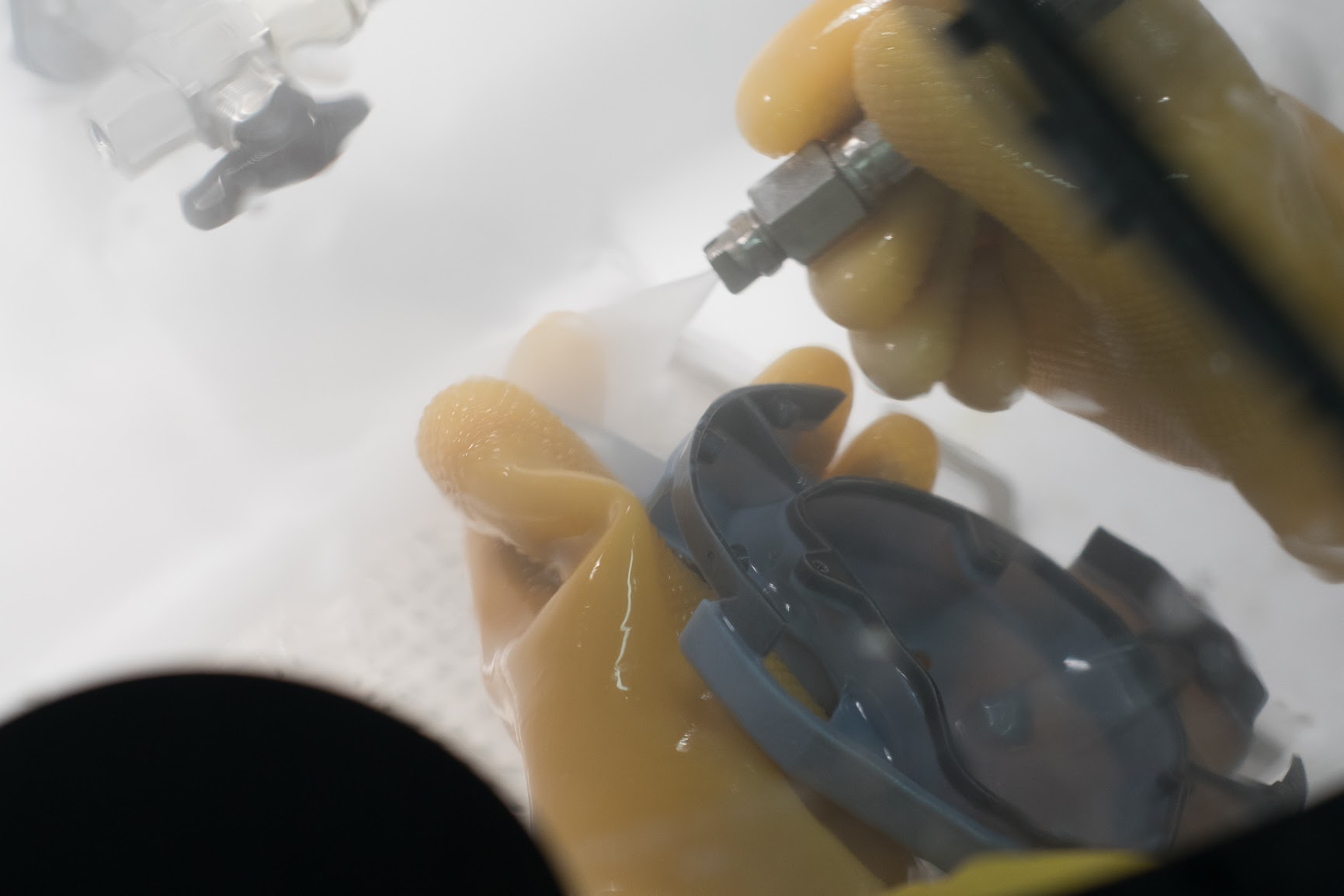
The most common post processing methods for Material Jetting are:
- Support removal
- Sanding
- Polishing
- Dying
- Metal plating
Rules of thumb
- Material Jetting produces highly accurate, detailed parts with a very smooth surface finish, representative of injection molded parts, making it an ideal solution for visual models and prototypes.
- The parts produced are brittle and not suitable for functional end use applications. For functional parts SLS or metal printing are better solutions.
- Material Jetting uses dissolvable support resulting in a good surface finish when compared to other support dependent technologies.
- Material Jetting is the only technology that can produce in full color and with flexible and stiff sections in a single build.
- Glossy surfaces must be orientated so that they are facing upright in relation to the build platform.
For designing Material Jetting part features:
| Feature | Design specifications |
|---|---|
| Major support walls | Minimum 1 mm in diameter. |
| All other walls | Minimum 0.5 mm in diameter. |
| Pin Diameter | Greater than 0.5 mm diameter. |
| Hole Size | Minimum diameter of 0.5mm |
| Embossed and engraved details | A minimum of 0.5 mm |
| Feature size (pins, protruding features etc.) | Can print features as low as 0.25 mm |
| Moving parts | Assembled parts, hinges and joints should have 0.15 – 0.2 mm clearance around all sides. |
| Tolerances | +/-0.1mm – 0.3mm depending on geometry and material |
