When the first direct metal laser sintering (DMLS) machines hit the production floor, some in the manufacturing community assumed the end of traditional machining was near. After all, how cool is it to fill a machine with metal powder, load a CAD file, and a few hours later, out pops a shiny new part? How could a shop possibly compete with a machine that creates little waste, has no cutting tools, and touts a setup as simple as the push of a button?
As it turns out, the reality of DMLS is slightly different than those early assumptions. No “Star Trek”-like replicators here, but rather a process that complements traditional machining. DMLS produces fully dense metal parts directly from CAD models, often with an accuracy and surface finish that allows a part to go directly into service. Most important, if you have a highly complex part that is impossible to machine, DMLS may be the answer.
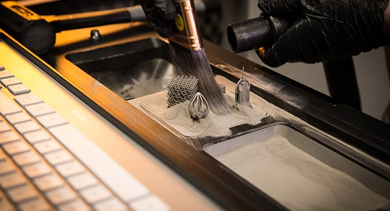
Like other laser-based 3D printing, or additive manufacturing, processes, DMLS builds parts from the bottom up. It uses an ytterbium laser to melt and fuse microscopic grains of metal powder into most any shape imaginable, provided it fits in a build chamber roughly the size of a microwave oven.
How Does Metal 3D Printing Work?
Let’s say that you just uploaded a 3D CAD model of your part design to protolabs.com. This could be anything from the next greatest fishing boat propeller to an air intake for an Indy car. Protolabs’ 3D printing technicians can turn that electronic dream into a physical reality in a few, relatively quick, steps:
- The CAD model is digitally sliced into paper-thin layers, and any needed support structures are designed in to aid in the laser sintering process. The file is then uploaded to one of our DMLS machines.
- The powder bed is filled with one of five high-strength alloys: aluminum, stainless steel, titanium, cobalt chrome, or Inconel. A thin layer of the material selected is then distributed across the build platform.
- As the build begins, a high-powered laser goes to work, drawing the bottom layer of the batch of parts, along with any temporary support structures necessary for the build process.
- A rubber wiper scrapes another thin layer of metal powder across the parts, and the lasing process is repeated.
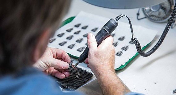
- Once complete, the nearly finished part is removed from the build chamber. The build supports are removed, and the parts may then be further processed per customer requirements.
That is essentially DMLS. As in every other 3D printing process, part quality is very dependent on a sound build strategy. For starters, DMLS requires support structures to hold features in place as the part is being built. Without them, flat areas may curl—a T-shape would turn into a Y, a dinner plate would become a pie tin. For the most part, Protolabs customers can leave support placement to the DMLS experts, but should understand that unsupported surfaces do tend to warp during the build, and secondary post processing will be needed to saw, grind, or machine those supports away.
DMLS Tolerances and Surface Finish
Part tolerance is another design consideration. High-resolution DMLS builds at a layer thickness of 0.0008 in. (0.02mm) and can produce quite accurate parts, with tolerances to +/- 0.003 in. (0.076mm), part features as small as 0.006 in. (0.152mm), and surface finishes similar to that of a sand casting. If you require a smoother finish, Protolabs offers a number of finishing operations, including bead blasting, hand polishing, and painting.
For those concerned about the metallurgical properties of laser-sintered parts, don’t be. DMLS uses laser power to actually melt individual metal particles. Each pass of the beam overlaps the previous one and re-melts the layer directly underneath, merging the metal into a homogenous mass that’s 99 percent as dense as conventionally formed materials.
The ability to create intricate internal features by “drawing” them one layer at a time opens the doors to previously impossible part designs. Complex structures and multi-part assemblies can be greatly simplified using DMLS. For example, GE Aviation reduced the part count in a fuel injector assembly from 18 to just 1 by using DMLS, and anticipates that more than 100,000 laser-sintered parts will be produced in this manner by 2020. And with the variety of alloys available, DMLS is enjoying increased use in the aerospace, medical, and consumer industries—everything from orthopedic implants and surgical tools to gas turbine and exhaust components are being produced today, in prototype and production quantities alike. The message here is that those who understand how to take advantage of metal laser sintering technology have highly complex metal parts manufactured with ease while reducing overall bill of materials (BOM).
Part of that understanding comes from knowing how DMLS works. Because parts are built in layers, so-called “stair stepping” will occur on angled surfaces—for example, the sides of a pyramid-shaped part will be rougher than those of a cube. Protolabs will attempt to orient the part build to minimize this effect, but it’s important to point out any critical surfaces or features when submitting your part design, so these can be placed in the horizontal build plane. Overly thick sections should be avoided wherever possible, as these add to build time and increase internal material stresses. And if very close tolerance holes or features are required, the design should include extra material for subsequent reaming or secondary machining. As always, a conversation with one of Protolabs’ applications engineers is recommended if any questions arise.
Remember that DMLS is not necessarily a faster, simpler alternative to machining. Part size is limited, since even a large-format DMLS machine maxes out at around 10 inches cubed at Protolabs. The upside to this is that the entire volume can be utilized—if you wanted to produce a thousand microscopic surgical instruments in 316 stainless steel, DMLS can make them in a single build. The process of melting metal one ultra thin layer at a time also isn’t terribly fast—our instruments may take a few days to build. For many parts, CNC machining remains the most economical choice. For everything else, DMLS may offer a number of advantages, chief among them design flexibility.
Lightweighting Parts with Metal 3D Printing
If you’re thinking about trying DMLS, another bit of advice is in order: Parts can be laser sintered far more quickly and at substantially less cost if they’re hollow. Unless you’re looking for the world’s most expensive paperweight, there’s no reason to melt every square inch of each powder layer when all that’s required is tracing enough of the outline to ensure its structural integrity. For this reason, DMLS is a great option for product designers aiming for lightweight parts—compared to machining, where lightweighting increases processing time and cost, DMLS is the opposite, becoming less expensive as part weight goes down.
This is an important point to aircraft and automobile manufacturers, where every ounce counts in terms of fuel efficiency. As mentioned previously, DMLS produces complex parts in lightweight material such as aluminum and titanium.
Ultimately, part design is a key factor in determining which process is best. Due to their complex three-dimensional shapes, tiny surgical instruments work well with laser sintering, whereas parts containing straightforward features—mounting brackets, manifold blocks, electronics housings, and many other components can be readily machined in lower volumes. Whichever way you go, it’s a brave new world of metal fabrication, one that Protolabs is well-equipped to help you explore.
How to Design Metal 3D Printed Parts
Now that we’ve discussed common applications and benefits of metal 3D printing technology let’s take a look at some basic guidelines on how to design features on metal 3D-printed parts.
Self-Supporting Angles
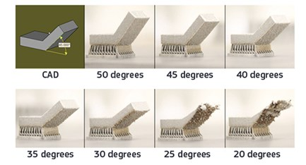
A self-supporting angle describes the feature’s angle relative to the build plate. The lower the angle, the less the likely it is to support itself. Each material will perform slightly different, but the general rule of thumb is to avoid designing a self-supporting feature that is less than 45 degrees. This tip will serve you well across all available materials. As you can see in the picture above, as the angle decreases, the part’s surface finish becomes rougher and eventually the part will fail if the angle is reduced too far.
Overhangs
Overhangs differ from self-supporting angles in that they are abrupt changes in a part’s geometry—not a smooth slope. DMLS is fairly limited in its support of overhangs when compared to other 3D printing technologies like stereolithography and selective laser sintering. Any overhang greater than 0.020 in. (0.5mm) should have additional support to prevent damage to the part. When designing overhangs it is wise to not push the limits as large overhangs can lead to reduction in a parts detail and worse, lead to the whole build crashing.
Channels and Holes
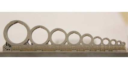
Internal channels and holes are one of the primary benefits of DMLS since they are impossible with other manufacturing methods. Conformal channels provide even cooling throughout a part and aid in reducing a component’s weight. It’s recommended that channels do not exceed a diameter of 0.30 in. (8mm). Similar to unsupported structures, as you exceed 0.30 in., the downward facing structures will become distorted. A tip to work around this constraint is to avoid designing circular channels. Instead, design channels with a tear drop or diamond shape. Channels that follow these shapes will make for a more uniform surface finish within the channel and allow you to maximize the channel’s diameter.
It’s recommended that channels do not exceed a diameter of 0.30 in. (8mm). Similar to unsupported structures, as you exceed 0.30 in., the downward facing structures will become distorted. A tip to work around this constraint is to avoid designing circular channels. Instead, design channels with a tear drop or diamond shape. Channels that follow these shapes will make for a more uniform surface finish within the channel and allow you to maximize the channel’s diameter.
Bridges
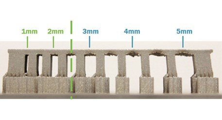
A bridge is any flat down-facing surface that is supported by 2 or more features. The minimum allowable unsupported distance we recommend is 0.080 in. In relation to other 3D printing technologies, this distance is relatively short due to the stresses of the rapid heating and cooling. In the picture below, you will see how the bridge pulls in the supporting structures as the unsupported distance increases. Parts that exceed this recommended limit will have poor quality on the downward facing surfaces and not be structurally sound.
Metal 3D Printing Materials Comparison Chart
There are a variety of metal alloys that can be 3D printed. Below is a side-by-side comparison of material properties between the available alloys.
| Material | Tensile Strength | 0.2% Yield | Elongation | Hardness |
|---|---|---|---|---|
Aluminum (AlSi10Mg) |
37.7 ksi | 20 ksi | 10% | 47.2 HRB |
Cobalt Chrome |
130 ksi | 75 ksi | 20% | 25 HRC |
Inconel 718 |
180 ksi | 150 ksi | 6-12% | 35.5 HRB |
Titanium (Ti-6Al-4V) |
129 ksi | 164 ksi | 10% | 40 HRC |
Stainless Steel 17-4PH |
190 ksi | 170 ksi | 8% | 40-47 HRC |
Stainless Steel 316L |
70 ksi | 25 ksi | 30% | 76.5 HRB – 25.5 HRC |
Post-Processing Metal 3D printed Parts
Once a part is finished building within the machine, several steps can be taken to improve its mechanical properties, surface finish quality, and ensure the part’s features are within tolerance.
Heat Treatment
Running parts through a heat treatment is necessary after a part is built as it will help relieve internal stresses that develop during the sintering process. The stresses in a build radiate outwards towards the edge of the part and build with each additional layer. For example, parts with thick cross sections will have more stress. There are a variety of heat treatment processes that can be used to address this:
- Vacuum furnace: Parts are placed inside a vacuum sealed furnace and then exposed to high heat environment thus reducing internal stresses.
- Hot isostatic pressing (HIP): Commonly referred to as HIP, this process applies both pressure and heat to the part in order to reduce porosity and increase density.
Post-Build CNC Machining
Some applications may require additional machining after the metal component is 3D printed. This is useful when tight tolerances or improved surface finish quality are required on specific features, but the overall geometry requires additive manufacturing to be produced. For example, a rocket engine component with complex cooling channels has a mating feature that requires a tolerance of +/- 0.001″. In some instances, post-build CNC machining can even be used to reduce costs due to less chips on the floor and more efficient use of materials.
Quality Inspections
Oftentimes metal parts built with additive manufacturing will require dimensional validation or an evaluation of the material’s microstructure. For this, coordinate measurement machines (CMM) can be used to verify part features are within tolerance. CT or X-ray scanning can also be used to examine internal features and provide a nondestructive solution to ensure structural integrity.
Learn More About Metal 3D Printing
If you would like to learn more about the DMLS and metal 3D printing in general, we have several other resources available. First, start by reading our white paper on manufacturing metal parts. This covers both machining and 3D printing and will help you decide which process will be best for your application.
