G-Code for CNC Machining
Even as new manufacturing technologies unfold, the fundamentals for how parts are machined with a CNC program will stay with you forever. In this article we’ll be talking about the core component of every CNC program – G-code.
G-Code at a Glance
Manufacturers all around the world use CNC programming to control a machine’s tools to produce parts. At the heart of this automated manufacturing process is a set of instructions that tells a CNC machine where – and how – to move. These instructions are called G-Code.
G-Code Blocks
The G-code standard was published back in the days when machines had small amounts of memory. Because of this memory limitation, G-code is an extremely compact and concise language that might almost seem archaic at first glance. Take for example this line of code:
G01 X1 Y1 F20 T01 M03 S500
In this single line we’re giving the machine a series of instructions:
- G01 – Perform a linear feed move
- X1/Y1 – Move to these X and Y coordinates
- F20 – Move at a feed rate of 20
- T01 – Use Tool 1 to get the job done
- M03 – Turn the spindle on
- S500 – Set a spindle speed of 500
Multiple lines of G-code like these combine to form a complete CNC program. Your CNC machine will then read the code one line at a time from left to right and top to bottom, like reading a book. Each set of instructions is on a separate line, or a block.
G-Code Programs
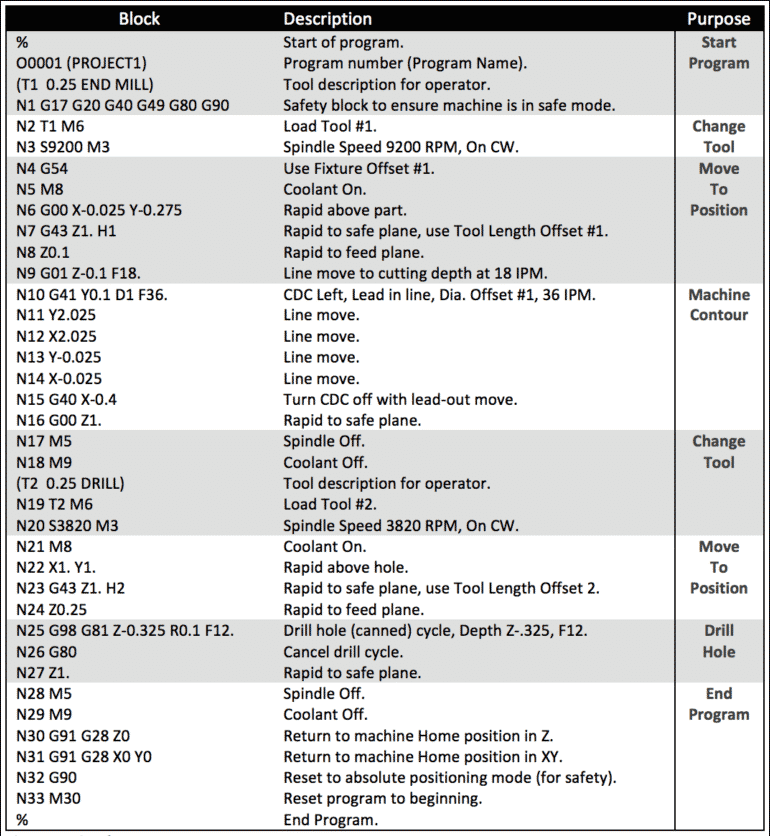
The goal of every G-code program is to produce parts in the safest and most efficient way possible. To achieve this you’ll typically find G-code blocks arranged in a very specific order like this:
- Start the CNC program
- Load the required tool
- Turn the spindle on
- Turn the coolant on
- Move to position above a part
- Start the machining process
- Turn the coolant off
- Turn the spindle off
- Move away from the part to a safe location
- End the CNC program
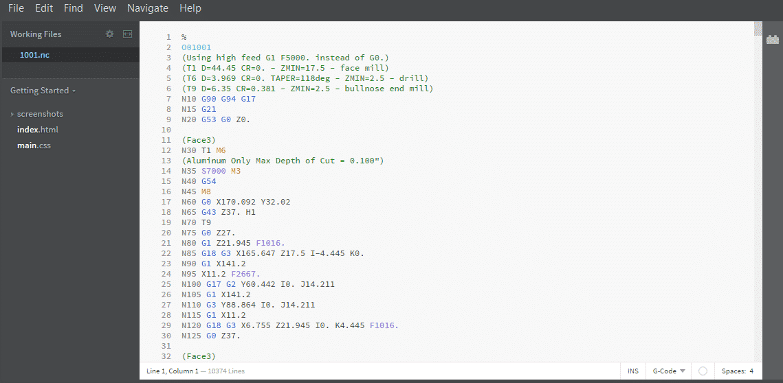
This flow is an extremely simple program using only one tool for one operation. In practice, you will typically rinse and repeat steps 2 through 9. For example, the G-code program below encompasses all of the code blocks above with repeating sections where needed:
G-Code in 3D Printing
In 3D printing, a part is created through the addition of material until a full part is created. In FDM 3D printing, this is accomplished by melting and extruding filament. 3D printing is very useful for creating custom parts and prototypes before a final design is reached.
Coincidentally, both 3D printers and CNC machines are controlled using G-code, which is a set of commands beginning with the letter “G” (as well as many other letters). Each command represents a micro-step in the process of crafting the final object. Among other things, G-code commands tell machines how to move and how to adjust settings, such as nozzle temperature on a 3D printer or cutting speed on a CNC. But even though both 3D printers and CNC mills use G-code, there are some significant differences in these two applications:
Several differences exist between 3D printing and CNC milling that affect their respective G-codes:
- The number of axes is different. As opposed to CNC mills, which traditionally have up to five axes, most 3D printers only have three. As such, many of the commands in the G-code library aren’t even used. Of course, exceptions exist, such as the Hyrel Hydra 3D printer that can print in 5 axes.
- 3D printer tools don’t spin. Unlike traditional CNC machines that utilize spinning mill bits, 3D printers deposit material layer by layer. Therefore, there isn’t any reason to use commands that set tool speed. Once again, there are some all-in-one machines that present exceptions, such as the ZMorph VX.
- 3D printers typically have fixed toolheads. Most 3D printers do not have removable hot ends that can be swapped out for more complex parts, whereas CNC mills can usually swap out bits to better perform different cuts. As always, exceptions exist in the 3D printing world, this time in the form of custom toolhead mounts.
- 3D printer G-Code consists primarily of G and M commands. Due to the relative simplicity of 3D printers, the two main command types that are used tend to be G and M codes. G-codes deal with moving motors and parts, while M-codes deal with machine-specific settings that tell the printer what to do. For example, an M-code exists for setting nozzle temperature on virtually every functional 3D printer. These M-codes vary by machine (for both 3D printing and CNC) and are therefore not standardized.