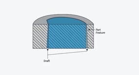
Press fits for injection-molded parts can be challenging. A well-designed injection-molded part will usually have draft, but the same draft that helps eject a part from the mold may also keep a press-fit part from staying firmly engaged. Consider a gear pressed onto a shaft (see Figure 1). In this case, the shaft has a “D”-shaped profile that acts as a drive flat and an orientation feature for assembly.
The drive flat keeps the gear from spinning freely on the shaft under load. Your molder will likely ask for draft on the D-hole to help release the feature from the mold. Draft is needed since as the resin cools, it shrinks onto the core that creates the hole. The request for draft is reasonable, but what if your design intent does not allow for draft? Here are a couple of options.

1. Leave the hole as-is and require the molder to support zero draft.
This is a risky request. If the hole is shallow enough you might not have any problems, but as the hole gets deeper, more stress is applied to the core of the mold during cooling and ejection. The increased force required for ejection could result in “pin punch” on the part, and increased ejection forces could result in breaking the core or ejector pins. The molder may have to tweak process parameters to prevent damage to the mold. This can increase the likelihood of imperfections like sink, porosity, and weak knit lines. Considering all the possible consequences, it makes sense to consider other options instead.
2. Add draft to the hole.
Draft allows the part to release from the mold because the shrinking part does not have to be forced along the same diameter shaft for the depth of the hole. If the hole is drafted, once the ejector system gives a slight bump to the part, the part releases from the mold because the draft falls away from the part wall. This reduces stress on both the part and the mold. Having a draft allows the molder the flexibility to use process tweaks to effectively address other geometric and cosmetic concerns. Draft solves the production problems, but your responsibility as the designer is to ensure that the draft doesn’t adversely affect the function of your assembly. For example, you would not want to have slop in the fit that could cause gear wobble (see Figure 2).

3. A good compromise option is to add crush ribs.
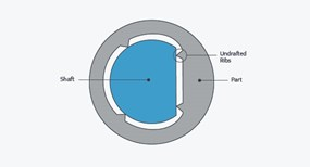
Crush ribs can give you the best of both approaches: draft for the molder and the same alignment you’d get with a straight-sided hole. The main hole is drafted for ease of ejection and protection of the mold, and three or more undrafted ribs along the length of the hole create a tight fit and good alignment with the shaft (see Figure 3).
Because the ribs present only a small surface area to the mold, their lack of draft creates little resistance to ejection and less risk of damage to the mold. The narrow points where the ribs meet the shaft (or other mating parts) allow the ribs to deform during press-fit to ensure a tight fit without creating a lot of stress on the part. Unfortunately, the sharp “V” features cannot be directly milled into the mold and thus require electrical discharge machining (EDM) or other extra processing during mold-making.

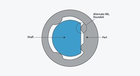
All is not lost, however. FacFox suggests an alternative rib shape that can be directly machined into the mold, minimizing cost. In place of the sharp point of the traditional “V”-shaped rib, consider a rounded rib (see Figure 4). A rounded rib can be directly created by milling, eliminating the need for EDM electrodes. It is faster and less expensive than a “V”-shaped alternative, and still provides the narrow, “crushable” point of contact with the mating part.
The same form can be used for ribs designed to create “standoff” where parts mate, for example where an air gap is needed. While FacFox offers EDM in some applications, we believe the full-radius rib created by an end mill is just as effective and reduces cost by minimizing mold complexity and manufacturing time. This reduction in time allows you to receive parts faster, test sooner, and bring your ideas to market before your competition.

