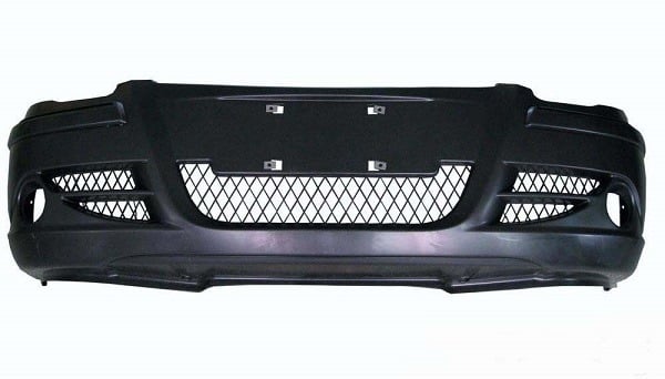
The bumper is one of the most easily damaged auto parts. Customers often face the following problems: if more than one percent of a bumper is damaged in a scratch or collision, the whole bumper must be scrapped; once the OEM label is torn off the bumper, the bumper can not be put back; and it takes time and money to reinstall a new bumper.
Many car lovers also like to customize bumpers to make their cars more personalized. Due to the sharp drop in the price of 3D printing and easier access to this technology, it has been widely used to replace bumpers with 3D printing.
After we have successfully produced some bumpers, we summarize the following design tips that are crucial for your reference.
Determine the wall thickness of the part
The wall thickness should be appropriate and as uniform as possible. There should be no sudden change, and the thickness should be gradually transitioned.
A lot of plastics have a certain range of suitable wall thickness, generally 0.5-4mm. When the wall thickness is more than 4mm, it will cause too long cooling time and problems such as sink marks. Consideration should be given to changing the product structure, and minimize wall thickness when meeting requirements.
Uneven wall thickness can cause surface shrinkage. It’s more obvious when you apply PP, POM, PE, PA, etc. The wall thickness of automobile exterior parts is generally 2.5 ± 0.25mm, and of large parts such as bumpers are 3 ± 0.25mm to 3.5 ± 0.25mm.
Design of Stiffener
The rational application of the stiffeners can increase the stiffness of the product and reduce deformation.
The thickness of the stiffener is generally not greater than 1/3 of the wall thickness of the product. Under special conditions (such as meeting the strength requirements), it must be less than 1/2 of the wall thickness of the product, otherwise, it will cause surface sink marks.
The slope of the stiffener on one side should be greater than 1.5 degrees to avoid cracking. The multiple stiffeners should be staggered and properly arranged, and the distance between them is greater than 4t (t is the wall thickness of the plastic part).
The height of the ribs is less than 3t, it should not be too large, otherwise, the ribs will be damaged by force.
Design of Support Surface
If the entire surface is used as the support surface of the part, slight deformation will affect the fit with the vehicle body. Therefore, in practice, convex edges or partially convex supporting angles are often used as the supporting structure.
Design of Hole
The various holes in the bumper must be provided at locations that do not weaken the mechanical strength of the product, and their shapes must also be convenient for mold manufacturing.
There should be a certain distance between the hole and the wall, and the minimum hole to the boundary is at least 1.5 times the hole diameter.
Material requirements for bumpers
- High toughness: In low-speed collisions, the material should decrease pedestrian injury and vehicle damage should be prevented.
- Appearance: It should allow for free design, no thermal deformation, insensitive to the environment, scratch resistance, no cracks, shrinkage, easy to spray.
License Installation Location
When the radius of the curvature of the bumper where you install the license is less than 6,000 mm, an uneven surface or a license plate mount should be made at the installation position.
Arrangement of hook cover
- The hook cannot be installed in the middle. It should be installed on the longitudinal beam of the frame and on both sides of the longitudinal beam. The longitudinal beams are much stronger than the transverse beams and can avoid frame deformation. The hooks must be placed on the same stringer before and after, so that the front and rear forces are on a line to prevent the frame from deforming.
- The bracket hook should be placed on the right side. Because the vehicle is driving on the right side, due to the friction of the vehicle, the amount of sinking on the right side of the vehicle is greater than the left side. Another reason is that when moving, the traction can move to the left so that the front and rear drivers can observe each other.
Requirements for energy-absorption blocks
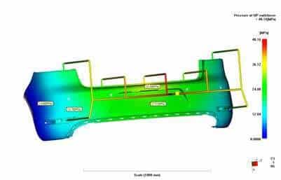
- Arrangement method of energy-absorbing block: Determine its spatial position according to the impact point of the impactor in GB17354-1998 (at half load, the impact point is on the horizontal plane of the impactor’s reference line, and the reference height is 445mm above the ground). During the collision, it is also necessary to meet the protection of the lower leg in pedestrian protection (the contact height between the front protection and the lower leg is 115mm). The specific size of the buffer block is determined based on the vehicle and CAE inspection.
- Buffer block material: Generally, a solid EPP foam structure is used. The material density is 46.5 kg / m², the compressive strength is 0.21 mPa, and the tensile strength is 0.66 mPa.